

Technical Overview
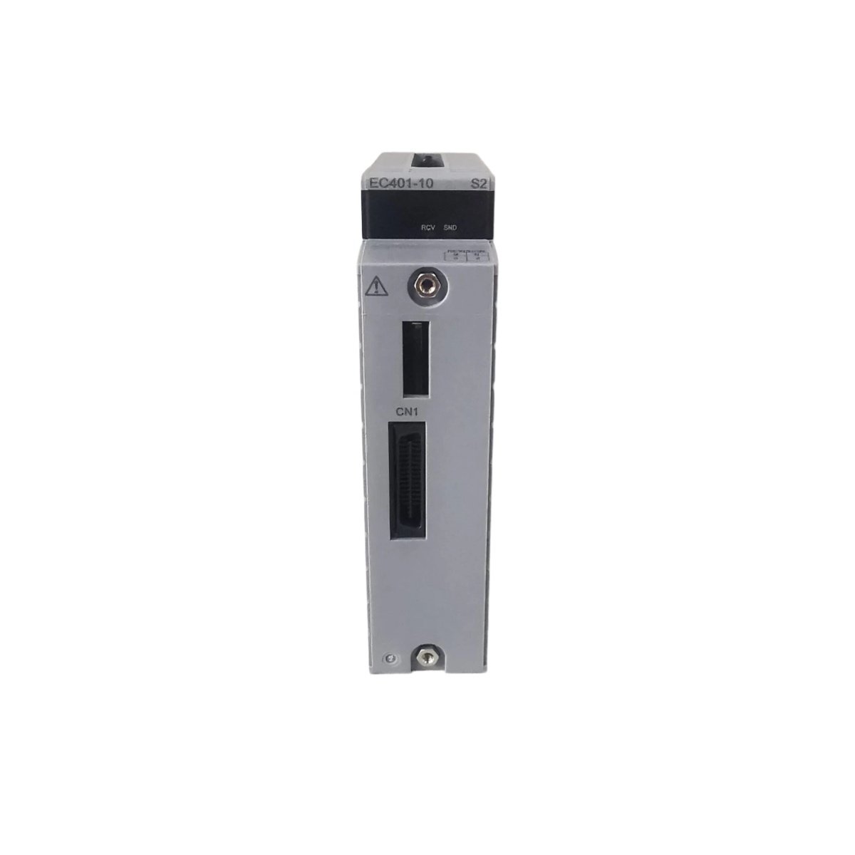
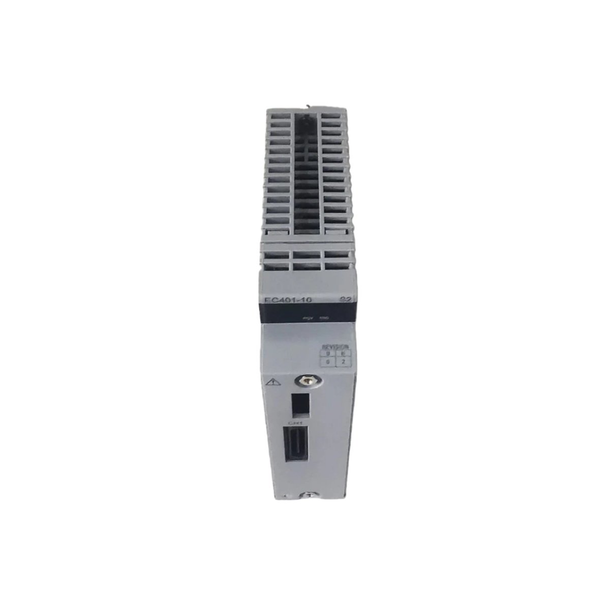
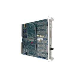
The EC401-10 S2 serves as an ESB bus coupler module for Yokogawa CENTUM VP distributed control systems. This advanced coupler provides high-speed data transfer between the ESB network and connected I/O nodes. Process automation facilities rely on this module for deterministic communication in critical control loops. The EC401-10 S2 features enhanced diagnostic capabilities for proactive maintenance and system health monitoring.
Key Specifications
| Parameter | Specification |
|---|---|
| Model | EC401-10 S2 |
| Bus Type | ESB (Extended Serial Bus) |
| Transmission Speed | 10 Mbps |
| Protocol | Yokogawa ESB protocol |
| Power Supply | 24 V DC nominal (20–30 V DC range) |
| Current Consumption | 180 mA (typical) |
| Isolation Voltage | 500 V AC (bus to logic) |
| Node Address Setting | Rotary switches (0–15) |
| Max Bus Cable Length | 50 m per segment |
| Number of Connectable Nodes | Up to 16 nodes |
| Diagnostic Features | Built-in self-test, error logging |
| Operating Temperature | 0°C to +55°C |
| Storage Temperature | -20°C to +75°C |
| Humidity Range | 10% to 95% RH (non-condensing) |
| Dimensions | 130 mm × 55 mm × 120 mm |
| Weight | 0.42 kg |
| Mounting Type | DIN rail |
| Redundancy Support | Dual-redundant configuration ready |
Communication and Bus Interface
The EC401-10 S2 handles ESB bus communication at a fixed speed of 10 Mbps for reliable data throughput. This coupler connects to the main controller through dedicated ESB ports and supports daisy-chain topology. Operators can assign node addresses from 0 to 15 using the front-accessible rotary switches. Two RJ45 connectors enable straightforward cabling between multiple couplers along the bus segment. The module also includes a built-in self-test function that verifies hardware integrity during startup. Front-panel LEDs provide immediate visual feedback for power, communication, and error conditions.
Power and Isolation Features
This bus coupler draws 180 mA from a 24 V DC supply with a tolerance of 20 to 30 V DC. The EC401-10 S2 integrates 500 V AC isolation between the field bus and the internal logic circuitry. This isolation barrier effectively eliminates ground loop interference and protects sensitive controller components. The module’s power consumption remains low despite its enhanced diagnostic features. Consequently, the coupler generates minimal heat, which promotes long-term operational stability.
Mechanical Construction and Installation
The EC401-10 S2 arrives in a robust DIN-rail mountable housing measuring 130 mm × 55 mm × 120 mm. Its weight of 0.42 kg makes it easy to handle during cabinet installation and maintenance procedures. The module operates reliably in ambient temperatures ranging from 0°C to 55°C. Storage conditions from -20°C to 75°C do not compromise its performance or longevity. With a humidity tolerance up to 95% RH, the coupler suits demanding plant environments with high moisture levels.
Redundancy and System Architecture
The EC401-10 S2 supports dual-redundant configurations for applications requiring maximum system availability. When you install two couplers in parallel, the system automatically switches to the standby unit during failures. This redundancy mechanism ensures uninterrupted communication between controllers and remote I/O stations. The module integrates flawlessly with CENTUM VP, ProSafe-RS, and other Yokogawa system platforms. Process engineers can also pair this coupler with various ESB-compatible I/O modules for flexible system design.
Application Areas and Benefits
The EC401-10 S2 finds extensive use in oil and gas, chemical, and pharmaceutical process industries. This coupler excels in distributed I/O architectures that demand high-speed, deterministic bus communication. Its enhanced diagnostics help maintenance teams identify potential issues before they escalate into costly failures. The module reduces cabling requirements by allowing multiple I/O nodes to share a single bus cable. Consequently, plant owners benefit from lower installation costs and simplified system engineering.
Operational Guidance
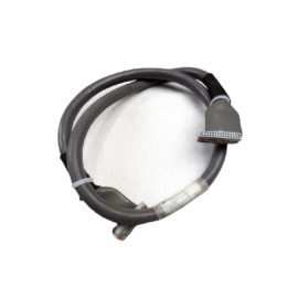
Mount the EC401-10 S2 securely onto a standard DIN rail within a suitable control cabinet. Connect the ESB cables firmly to the RJ45 ports, observing proper cable routing practices. Set the rotary address switches to the desired node number before applying power to the module. Regularly inspect the LED indicators to confirm normal operation and bus activity. The module requires no regular calibration, so maintenance schedules remain minimal. For detailed fault isolation, refer to the error log accessible through the system diagnostic interface.
Details
| Weight | 0.42 kg |
|---|---|
| Dimensions | 130 × 55 × 120 mm |
Reviews
There are no reviews yet.