
Primary Coupling Function and Network Role
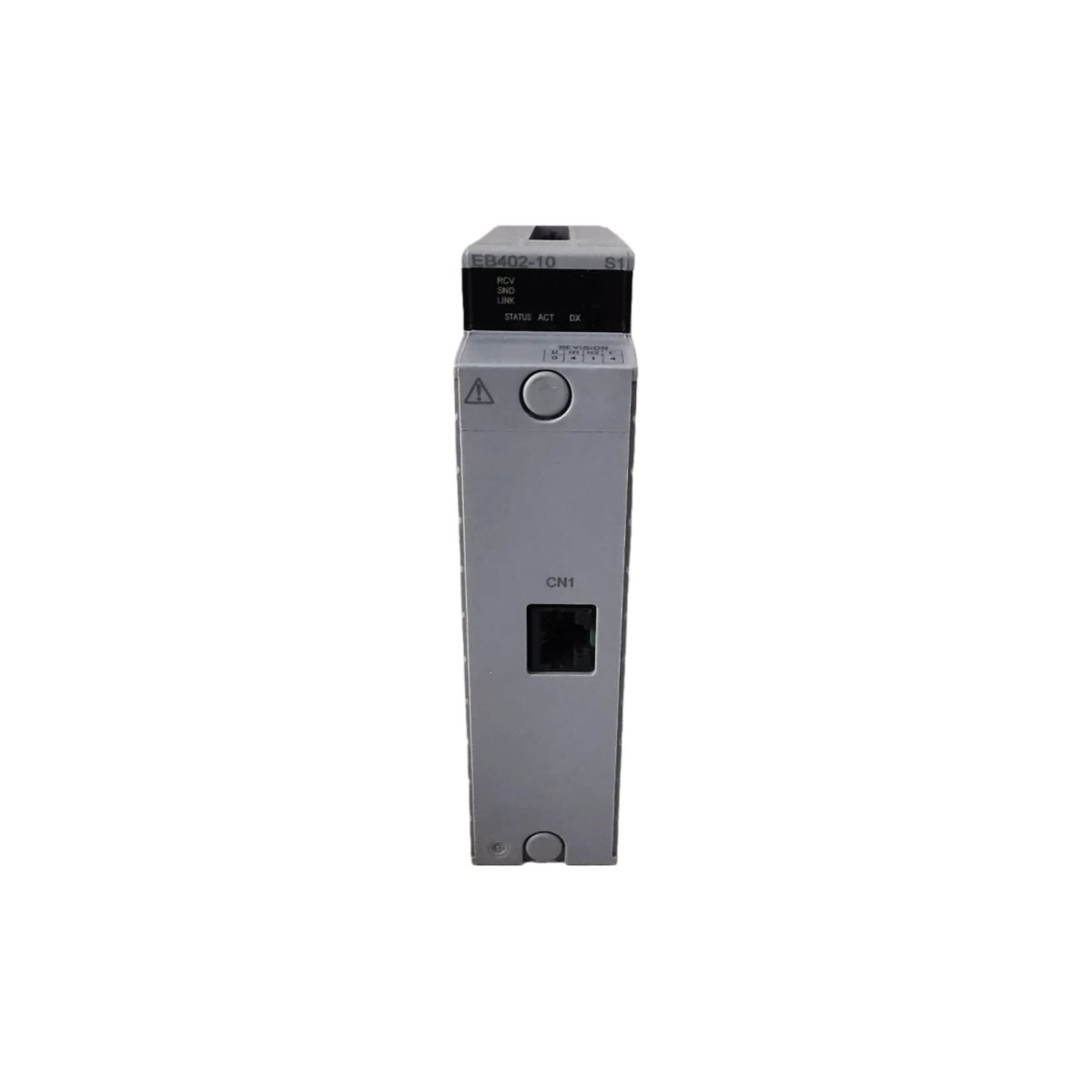
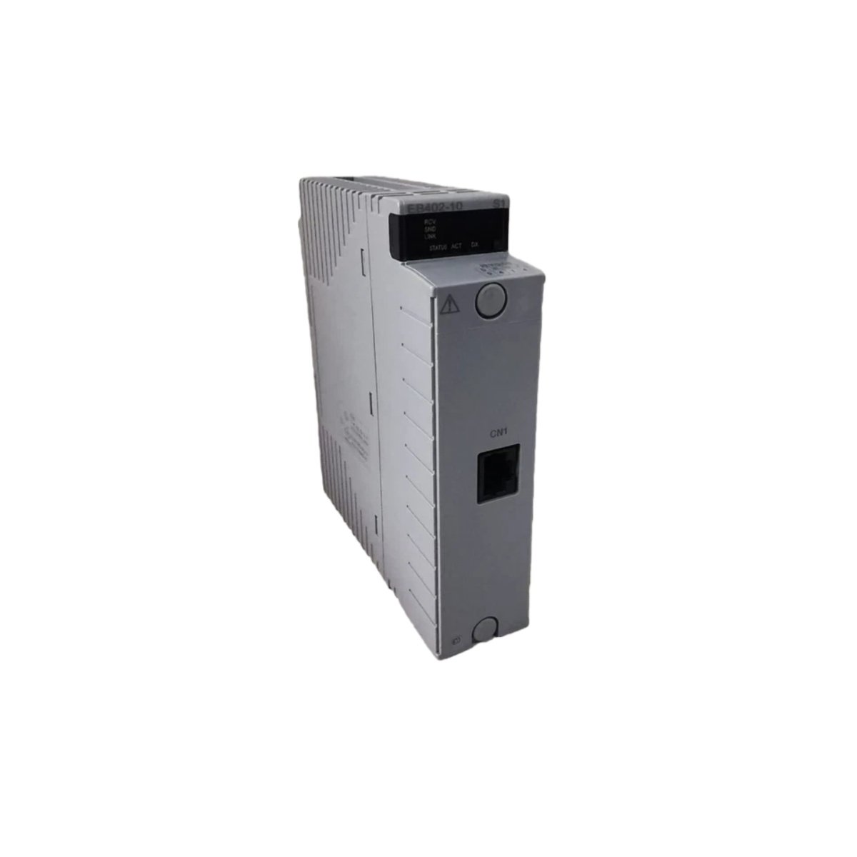
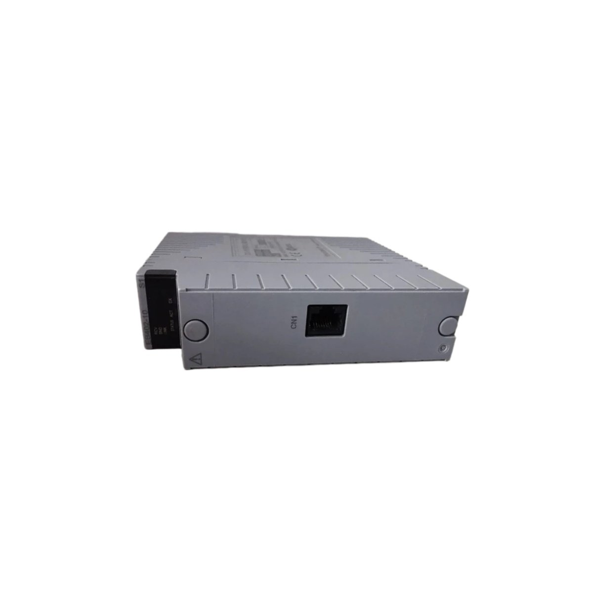
This ESB bus coupler module bridges the central controller with remote I/O nodes in Yokogawa DCS systems. It translates communication protocols between the backplane bus and the fieldbus network seamlessly. You can deploy this unit in distributed control architectures requiring high-speed data exchange. The coupler actively manages data flow in both directions without introducing significant latency. It automatically synchronizes its timing with the master controller’s scan cycle. This module simplifies system expansion and reduces field wiring complexity.
Physical Dimensions and Chassis Installation
The Yokogawa EB402 measures 250.0 mm in height and 45.0 mm in width. Its depth reaches 180.0 mm from the front face to the rear connector. This unit weighs approximately 1.60 kg, requiring careful handling during installation. You can slide this module into any standard Yokogawa chassis slot. Two locking ejector handles secure the unit firmly in its operational position. The robust aluminum housing provides excellent thermal dissipation and mechanical protection.
Bus Interface Specifications and Data Rates
This coupler features one ESB bus port for connection to the main controller. It also provides one扩展bus port for daisy-chaining additional coupler modules. The Yokogawa EB402 supports data transfer rates up to 2.5 Mbps. You can configure the communication speed through the system engineering software. The module automatically negotiates the optimal baud rate with connected devices. This flexibility ensures compatibility with various fieldbus network configurations.
Channel Capacity and Node Management
This coupler supports up to 16 connected I/O modules per ESB bus segment. It manages data exchange for a maximum of 256 discrete input points and 256 discrete output points. The Yokogawa EB402 also handles analog signals with 16-bit resolution. You can mix digital and analog modules freely on the same bus segment. The module maintains a dynamic node table for active device monitoring. This management capability simplifies system configuration and diagnostics.
Memory Resources and Data Buffering
The module incorporates 256 KB of SRAM for temporary data storage and buffering. It also includes 128 KB of flash memory for firmware and configuration retention. The Yokogawa EB402 uses an additional 16 KB EEPROM for storing network parameters permanently. You can configure the buffer size for different application requirements. The processor manages read and write operations without data collisions. This memory architecture ensures smooth data flow during peak network activity.
Internal Component Architecture
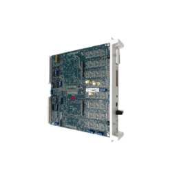
The main PCB contains a dedicated communication controller with integrated bus arbitration. You will find high-speed optocouplers providing 2.5 kV isolation on the bus ports. The Yokogawa EB402 uses a temperature-compensated crystal oscillator for precise timing. A robust transceiver drives the ESB bus signals with minimal distortion. The board includes over 120 discrete components including capacitors and resistors. This design emphasizes reliability for continuous process control applications.
Power Consumption and Energy Backup
This coupler module draws 320 mA from the 5 VDC backplane supply during operation. It also consumes 60 mA from the 24 VDC field power input. An internal 1.0 F supercapacitor provides short-term energy for graceful shutdown. This capacitance sustains the module during brief power interruptions. The unit also features a replaceable 3.0 V lithium battery for real-time clock backup. This battery maintains the clock and diagnostic logs for over 5 years.
Environmental Specifications and Certifications
The Yokogawa EB402 operates reliably between 0°C and 60°C ambient temperature. It withstands relative humidity from 10% to 95% without condensation issues. The enclosure meets IP20 protection standards for indoor control room use. Vibration tolerance reaches 2 G from 10 Hz to 150 Hz on each axis. Shock resistance measures 15 G for 11 milliseconds half-sine pulses. These qualifications suit applications in chemical and power generation industries.
Technical Data Summary
| Parameter | Specification |
|---|---|
| Brand | Yokogawa |
| Model | EB402 |
| Type | ESB Bus Coupler Module |
| Dimensions (H × W × D) | 250.0 × 45.0 × 180.0 mm |
| Weight | 1.60 kg |
| Bus Interface | ESB bus port +扩展bus port |
| Data Transfer Rate | Up to 2.5 Mbps |
| Maximum I/O Modules | 16 per segment |
| Digital Points | 256 inputs / 256 outputs |
| Analog Resolution | 16-bit |
| Data Buffer | 256 KB SRAM |
| Firmware Memory | 128 KB Flash |
| Configuration Memory | 16 KB EEPROM |
| Backplane Current | 320 mA at 5 VDC |
| Field Current | 60 mA at 24 VDC |
| Isolation | 2.5 kV optocouplers |
| Supercapacitor | 1.0 F |
| Battery | 3.0 V Lithium (5+ years) |
| Temperature Range | 0 to 60 °C |
| Protection Rating | IP20 |
Diagnostic Features and Status Indication
This module provides multiple LED indicators for comprehensive status monitoring. Green LEDs show power, run, and bus communication activity status. Red LEDs alert you to communication errors or node failures. You can access diagnostic information through the system engineering software. The module also stores the last 30 error events in non-volatile memory.
Details
| Weight | 1.60 kg |
|---|---|
| Dimensions | 250 × 45 × 180 mm |
Reviews
There are no reviews yet.