
Product Overview
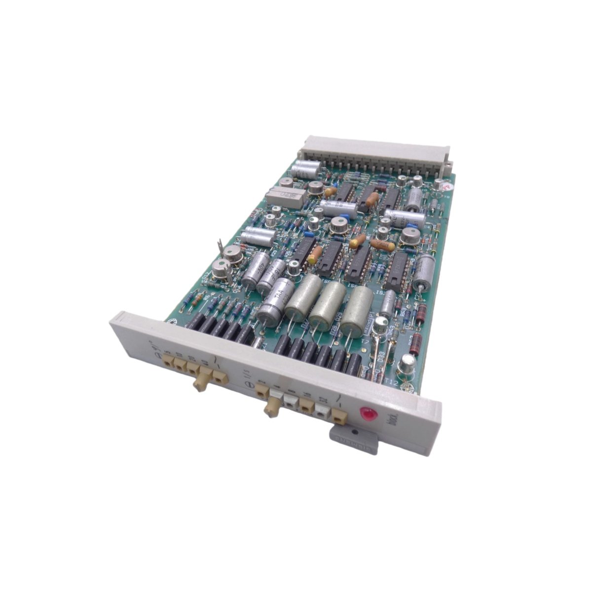
This interface module bridges field devices with SIMATIC backplane communication networks. Process plants require reliable signal translation between diverse equipment and central controllers. The 7TL4400-0/CC converts digital and analog signals into standardized bus data formats. Its compact housing fits standard DIN-rail mounting without complex installation procedures. System integrators value the plug-and-play compatibility with existing Siemens components. The unit provides galvanic isolation to eliminate troublesome ground-loop currents.
Technical Specifications
| Parameter | Specification |
|---|---|
| Digital Input Channels | 8 optically isolated, 24 VDC |
| Digital Output Channels | 8 transistor outputs, 24 VDC / 0.5A |
| Analog Input Channels | 4 differential, 0–10 V or 4–20 mA |
| Analog Output Channels | 2 isolated, 0–10 V or 4–20 mA |
| Communication Protocol | PROFIBUS DP (via backplane) |
| Data Transfer Rate | 9.6 kbps to 12 Mbps (auto-detecting) |
| Bus Connector | 9-pin D-sub (standard assignment) |
| Addressing | Rotary switches (0–99) |
| Isolation Voltage | 2500 VAC (I/O to bus) |
| Analog Resolution | 14-bit (input), 12-bit (output) |
| Accuracy at 25°C | ±0.15% of full scale |
| Supply Voltage | 24 VDC ±20% (from backplane) |
| Power Consumption | ≤6.0 W |
| Operating Temperature | –10°C to +60°C |
| Storage Temperature | –40°C to +85°C |
| Dimensions (W x H x D) | 45 mm x 130 mm x 128 mm |
| Weight | 0.42 kg |
| Mounting Type | DIN-rail (35 mm) with spring clip |
| Termination | Screw-type terminal blocks (removable) |
Signal Translation and Protocol Conversion
The 7TL4400-0/CC translates raw I/O signals into PROFIBUS DP telegrams for the host controller. Its integrated communication processor handles all bus protocol overhead automatically. Digital inputs capture switch states and transmit them as Boolean data objects. Analog signals undergo A/D conversion before packaging into cyclic data frames. The module receives output commands from the bus and converts them to appropriate field signals.
Analog and Digital I/O Integration
Four analog input channels accept standard process signals with 14-bit resolution. Two analog output channels provide controlled voltage or current signals to final control elements. Eight digital input channels detect 24-volt signals from pushbuttons and proximity sensors. Eight digital output channels drive indicator lamps, relays, and small solenoids. All channels include transient suppression to prevent damage from inductive load switching.
Configuration and Network Addressing
Dual rotary switches on the front panel set the node address from 0 to 99. The module automatically detects the PROFIBUS baud rate during network initialization. Configuration parameters reside in non-volatile memory for rapid reconnection after power cycles. The unit stores diagnostic data for the last ten communication errors. Users can configure channel-specific scaling and filtering through the engineering software.
Diagnostics and Fault Annunciation
Individual LEDs display power status, bus activity, and I/O channel health conditions. A group fault LED illuminates when any channel exceeds its operating limits. The module generates diagnostic telegrams for transmission to the central controller. Short-circuit and open-load detection protect field devices from damage. Cyclic redundancy checks ensure data integrity on all bus transactions.
Mechanical Construction and Field Wiring
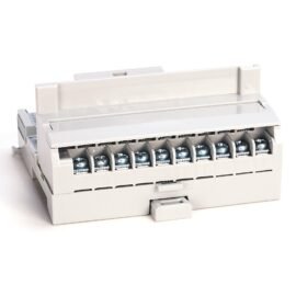
The 45-millimeter housing accommodates all connections on the front face for easy access. Removable terminal blocks accept solid and stranded wires from 0.2 mm² to 2.5 mm². The module weighs 420 grams and clips securely onto standard DIN rails. All terminals feature clear numerical labeling for straightforward wiring verification. The unit’s shallow 128-millimeter depth enables installation in compact enclosures.
Details
| Weight | 0.42 kg |
|---|---|
| Dimensions | 45 × 130 × 128 mm |
Reviews
There are no reviews yet.