
Product Overview
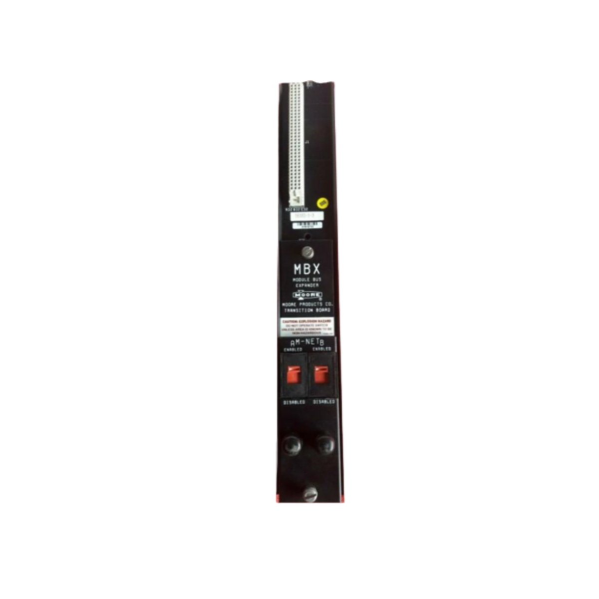
The Siemens 16182-1-3 serves as a transition board for MBX system backplane connections. This board adapts signal routing between different interface standards and pin configurations. It provides reliable interconnection for Siemens industrial control systems. The unit fits into Siemens SIMATIC and other compatible cabinet installations.
Technical Specifications
| Parameter | Specification |
|---|---|
| Model Number | 16182-1-3 |
| Product Type | MBX Transition Board |
| Connector Type 1 | 64-pin Eurocard connector (DIN 41612) |
| Connector Type 2 | 40-pin header connector |
| Number of Layers | 4-layer PCB |
| PCB Material | FR-4 glass epoxy |
| Contact Plating | Gold-plated contacts |
| Operating Voltage | 5 VDC and 24 VDC |
| Signal Levels | TTL and 24 VDC compatible |
| Termination | Solder pins for wire connections |
| Mounting Holes | 4 corner mounting points |
| Operating Temperature | 0°C to 60°C |
| Storage Temperature | –40°C to 85°C |
| Humidity Range | 5% to 95% non-condensing |
Physical Dimensions and Construction
This transition board measures approximately 160 mm in width and 100 mm in height. The unit weighs roughly 0.20 kg with all components installed. It features a 4-layer FR-4 PCB with plated-through holes. The board includes gold-plated connector contacts for reliable signal transmission. Four mounting holes at the corners provide secure mechanical attachment.
Electrical Interface and Connectivity
The 16182-1-3 incorporates a 64-pin Eurocard connector on one end for backplane interfacing. The opposite side features a 40-pin header for ribbon cable connections. Each pin carries signals between the two interface standards. The board routes TTL and 24 VDC signals through the transition circuits. Color-coded test points allow for easy signal verification during commissioning. The solder pins on the board accept wire connections for additional signal access.
Signal Integrity and PCB Layout
This transition board maintains signal integrity through careful impedance-controlled routing. The 4-layer design provides dedicated power and ground planes. These planes reduce crosstalk and electromagnetic interference effectively. The board includes decoupling capacitors near the power pins for noise suppression. Consequently, signal quality stays consistent across the entire transition path.
Installation and System Integration
You can mount this board onto the backplane using the provided Eurocard connectors. Secure the board with screws through the four mounting holes. Always align the connector pins carefully before seating the board. Use the correct ribbon cable orientation when connecting to the header. Verify signal continuity using the test points before powering up the system.
Environmental Compliance
This board meets RoHS requirements for restricted substance compliance. It also carries UL recognition for industrial control equipment. The PCB material complies with standard fire safety ratings.
Details
| Weight | 0.58 kg |
|---|---|
| Dimensions | 45 × 230 × 140 mm |

Reviews
There are no reviews yet.