
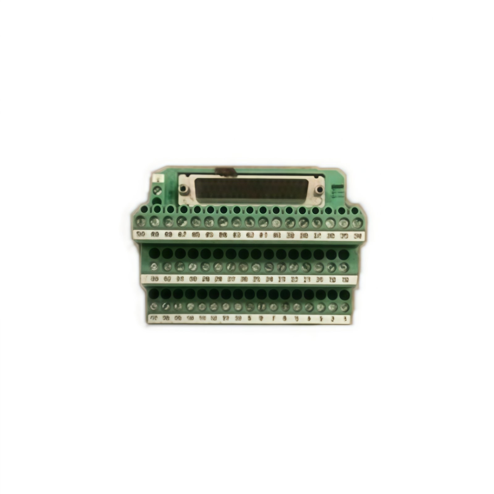
Breakout Architecture and System Interface
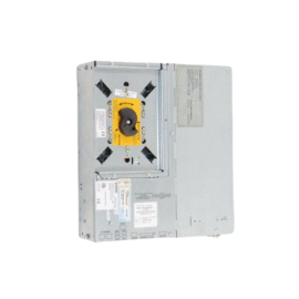
This breakout module provides a convenient wiring interface for Schneider Quantum I/O systems. It breaks out a 50-pin ribbon cable into individual screw terminals for field wiring. The module supports up to 32 I/O points in a single compact assembly. Each terminal provides clear labeling for simple and accurate connection. Consequently, this unit simplifies cabinet installation and maintenance tasks.
Technical Specifications
| Parameter | Specification |
|---|---|
| Brand | Schneider Electric |
| Model Number | 690MCB00000 |
| Termination Points | 32 I/O channels |
| Connector Type | 50-pin ribbon cable (input) |
| Termination Style | Screw-clamp terminals |
| Wire Gauge | 14–22 AWG |
| Contact Material | Nickel-plated brass |
| Terminal Pitch | 5.08 mm |
| Voltage Rating | 250 VAC / 125 VDC |
| Current Rating | 2 A per terminal |
| Insulation Resistance | >100 MΩ at 500 VDC |
| Dielectric Strength | 2000 VAC for 1 minute |
| Operating Temperature | –25°C to +70°C |
| Storage Temperature | –40°C to +85°C |
| Humidity | 5% to 95% non-condensing |
| Dimensions (H x W x D) | 140 mm x 180 mm x 65 mm |
| Weight | 0.55 kg |
| Mounting | 35 mm DIN-rail or panel |
| Labeling | Pre-printed marker strip |
| Accessories | Screwdriver and mounting clips |
Signal Routing and Termination Design
The 690MCB00000 receives a 50-pin ribbon cable from the Quantum I/O module. It routes each signal to an individual screw terminal for field wiring. The module assigns each pin to a specific channel according to the pinout. This breakout arrangement simplifies field connections and troubleshooting. Users can easily access individual wires without disturbing other terminations.
Field Wiring and Connection Security
Screw-clamp terminals provide reliable connections for solid or stranded wires. Each terminal accepts wires from 14 to 22 AWG for flexibility. The module includes a common ground bus bar for return signal consolidation. A clear numbering system matches each terminal to its corresponding I/O point. This design minimizes wiring errors and speeds up installation.
Installation and Mounting Instructions
Mount the module on a 35 mm DIN-rail using the integrated spring clips. Alternatively, secure it to a panel with the provided mounting holes. Connect the 50-pin ribbon cable from the I/O module first. Then route and terminate field wiring at the screw terminals. Tighten each terminal screw to 0.5–0.6 Nm for reliable connections.
Construction Quality and Durability
The housing uses high-strength polyamide for mechanical durability. Terminal contacts feature nickel-plated brass for corrosion resistance. The PCB employs FR-4 glass-epoxy laminate for reliable insulation. This robust construction ensures long-term service in industrial settings. The module meets all relevant safety and performance standards.
Environmental Performance and Maintenance
The module operates reliably from –25°C to +70°C ambient temperature. It withstands humidity between 5% and 95% without condensation. The unit requires minimal maintenance beyond periodic inspection. Check terminal tightness during routine system checks. Replace the module if terminal connections become damaged.
Details
| Weight | 0.55 kg |
|---|---|
| Dimensions | 140 × 180 × 65 mm |
Reviews
There are no reviews yet.