
Product Overview
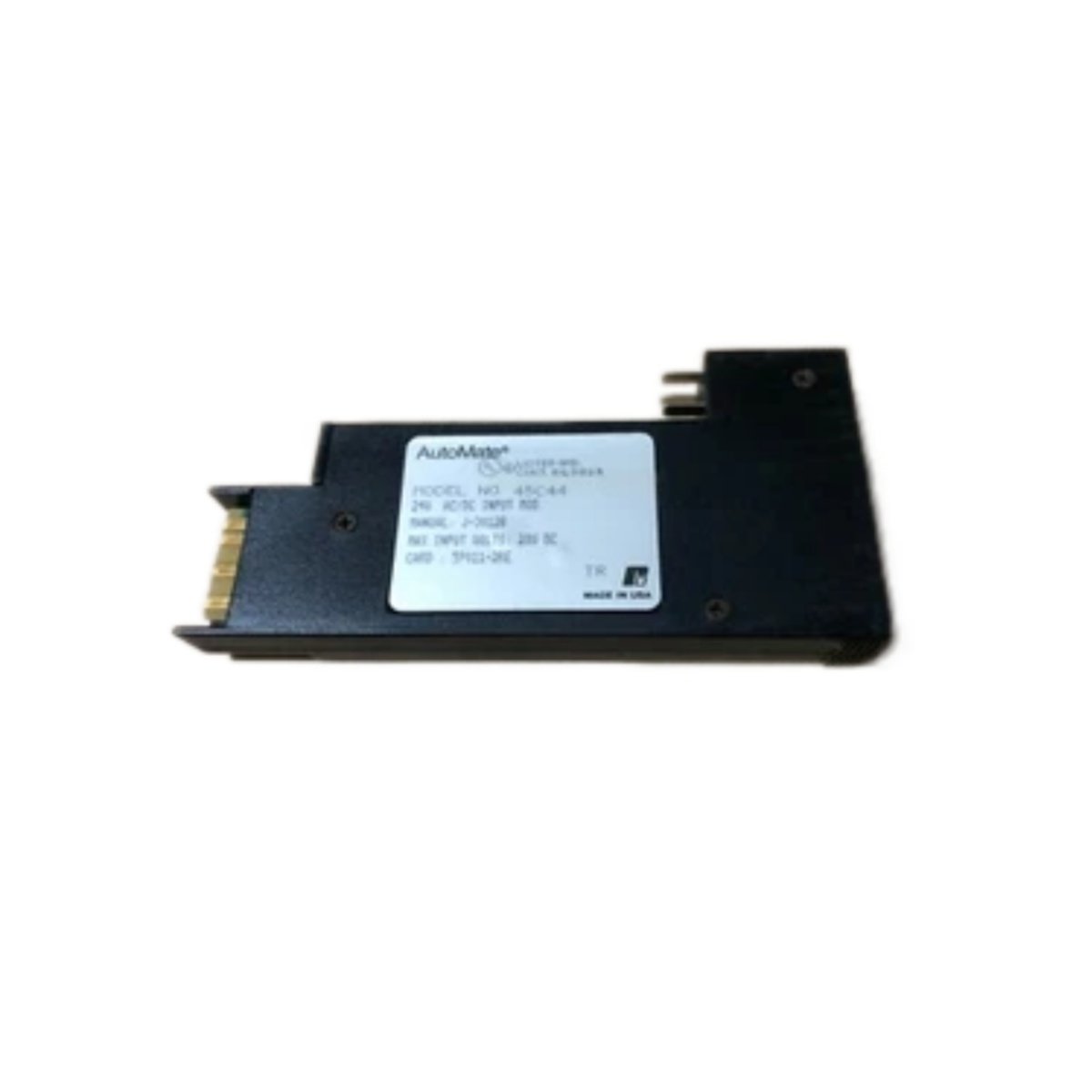
This 19-slot rack provides extensive I/O capacity for large-scale Reliance Electric automation systems. Plant-wide control applications demand sufficient space for multiple modules and expansion cards. The 45C319 accommodates up to nineteen modules in a single 19-inch chassis. Its robust backplane distributes power and data reliably across all installed units. System designers can populate this rack with processors, I/O modules, and communication interfaces. The rack’s ventilated design supports natural convection cooling for densely populated configurations.
Technical Specifications
| Parameter | Specification |
|---|---|
| Number of Module Slots | 19 (universal, keyed) |
| Rack Width | 19 inches (482.6 mm) standard |
| Rack Height | 7U (311.2 mm) |
| Rack Depth | 200 mm (from front to rear) |
| Slot Pitch | 20.32 mm (0.8 inches) |
| Backplane Type | Multilayer PCB with active termination |
| Bus Structure | Parallel data/address (16-bit) plus serial |
| Connector Type per Slot | 96-pin DIN 41612 (male) |
| Power Distribution | 5 VDC (25 A), ±15 VDC (10 A), 24 VDC (15 A) |
| Chassis Ground | M6 stud with copper bus bar |
| Cooling | Natural convection (ventilated panels) |
| Mounting Type | 19-inch rack or cabinet rails |
| Material | Cold-rolled steel (1.5 mm thickness) |
| Finish | Powder-coated, RAL 7032 (light gray) |
| Weight (empty) | 6.2 kg |
| Weight (fully populated) | Approximately 15 kg (with modules) |
| Dimensions (W x H x D) | 482.6 mm x 311.2 mm x 200 mm |
| Operating Temperature | 0°C to +55°C |
| Storage Temperature | –40°C to +85°C |
| Included Accessories | Mounting ears, hardware kit, slot fillers |
Module Accommodation and Slot Configuration
The 45C319 features nineteen universal slots with keyed guides for correct module insertion. Each slot uses a 96-pin DIN 41612 connector for robust signal and power connectivity. The rack’s 7U height provides additional space for larger modules and better airflow. Slot pitch of 20.32 millimeters ensures compatibility with standard Reliance module form factors. The unit supports mixed configurations of digital, analog, and communication modules.
Backplane Architecture and Data Distribution
The multilayer backplane includes dedicated planes for power, ground, and signal routing. Active termination on the backplane improves signal integrity at high bus speeds. The bus structure supports both parallel and serial data transfer protocols. Voltage planes deliver 5 VDC, ±15 VDC, and 24 VDC to every slot independently. The backplane design minimizes crosstalk between adjacent high-speed signal traces.
Power Capacity and Distribution
This rack provides substantial power capacity for heavily populated configurations. The 5-volt bus delivers up to 25 amperes for logic and processor modules. ±15-volt supplies provide 10 amperes for analog circuits and instrumentation. The 24-volt bus offers 15 amperes for field I/O and communication modules. Input fuses protect each voltage rail against overcurrent events. Users should calculate total load to remain within these capacity limits.
Mechanical Construction and Weight Considerations
The cold-rolled steel chassis provides excellent mechanical rigidity for long-term reliability. The 1.5-millimeter thick panels resist flexing during module insertion and extraction. An empty rack weighs 6.2 kilograms, while a fully populated unit reaches approximately 15 kilograms. Proper rail support is essential for installations requiring seismic or vibration compliance. The powder-coated finish resists scratches and corrosion in industrial environments.
Cooling and Thermal Performance
Ventilation slots on the top, bottom, and side panels promote natural convection airflow. The 7U height provides increased vertical clearance for heat dissipation from densely populated racks. Modules should draw air from the bottom and exhaust through the top for efficient cooling. Users should maintain at least 50 millimeters clearance above and below the rack. The unit’s thermal design supports full loading at 55°C ambient temperature.
Grounding and Electromagnetic Compatibility
A dedicated M6 chassis ground stud provides a low-impedance path to protective earth. The copper bus bar ensures equal potential across the entire rack assembly. Steel construction attenuates radiated electromagnetic interference from nearby equipment. Shielded backplane traces reduce conducted emissions on signal lines. The assembly meets EMC requirements for industrial control equipment installations.
Installation and System Expansion
Mounting ears with hardware secure the rack to standard 19-inch cabinet rails. The 200-millimeter depth fits most industrial enclosure depths. Clear labeling on the backplane identifies slot numbers and test points. Expansion connectors allow interconnection with additional racks in larger systems. The unit’s modular architecture supports system growth without replacing existing infrastructure.
Details
| Weight | 6.2 kg |
|---|---|
| Dimensions | 482.6 × 311.2 × 200 mm |
Reviews
There are no reviews yet.