
Product Overview
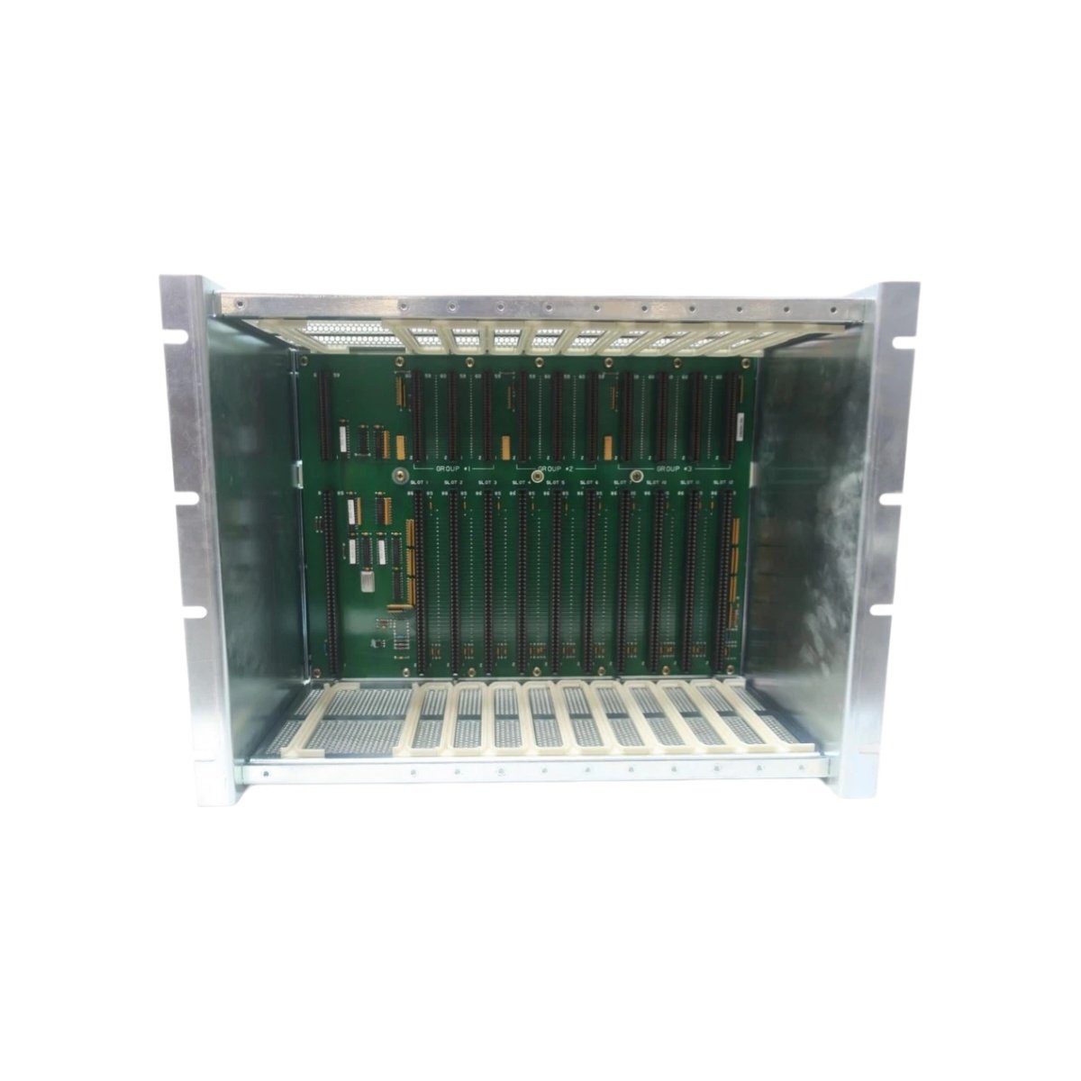
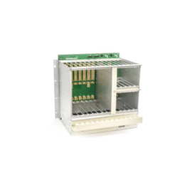
This card rack assembly houses multiple I/O modules in a structured and organized manner. Control cabinets benefit from this modular approach to system expansion and maintenance. The 45C314 accommodates up to twelve modules in a single 19-inch rack. Its rugged steel construction provides mechanical support and electromagnetic shielding. System integrators can populate this rack with various input, output, and communication modules. The assembly’s backplane wiring simplifies connections between modules and the controller.
Technical Specifications
| Parameter | Specification |
|---|---|
| Number of Module Slots | 12 (universal, keyed) |
| Rack Width | 19 inches (482.6 mm) standard |
| Rack Height | 6U (266.7 mm) |
| Rack Depth | 200 mm (from front to rear) |
| Slot Pitch | 20.32 mm (0.8 inches) |
| Backplane Type | Passive, multilayer PCB |
| Bus Structure | Parallel data/address bus (16-bit) |
| Connector Type per Slot | 96-pin DIN 41612 (male) |
| Power Distribution | 5 VDC, ±15 VDC, 24 VDC via backplane |
| Maximum Current Capacity | 20 A (5V), 10 A (±15V), 15 A (24V) |
| Fusing | Input mains fuse and per-voltage fuses |
| Grounding | Chassis ground stud (M6) with star configuration |
| Cooling | Natural convection (ventilated top/bottom) |
| Mounting Type | 19-inch rack or cabinet rails |
| Material | Cold-rolled steel (1.5 mm thickness) |
| Finish | Powder-coated, RAL 7032 (light gray) |
| Weight (empty) | 4.8 kg |
| Weight (fully populated) | Approximately 10 kg (with modules) |
| Dimensions (W x H x D) | 482.6 mm x 266.7 mm x 200 mm |
| Operating Temperature | 0°C to +55°C |
| Storage Temperature | –40°C to +85°C |
Physical Construction and Module Accommodation
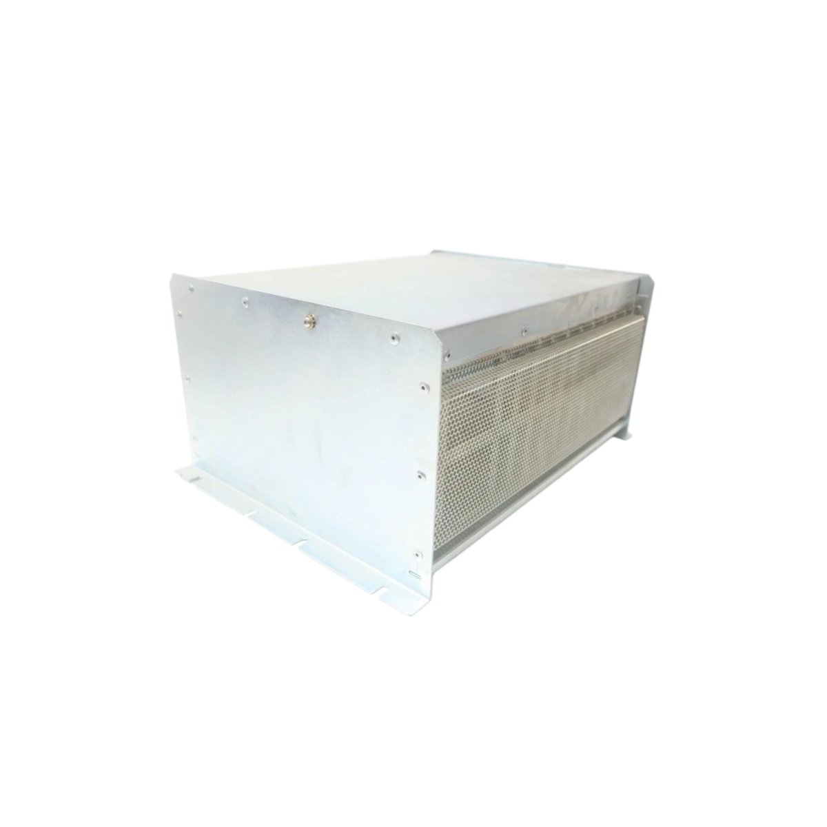
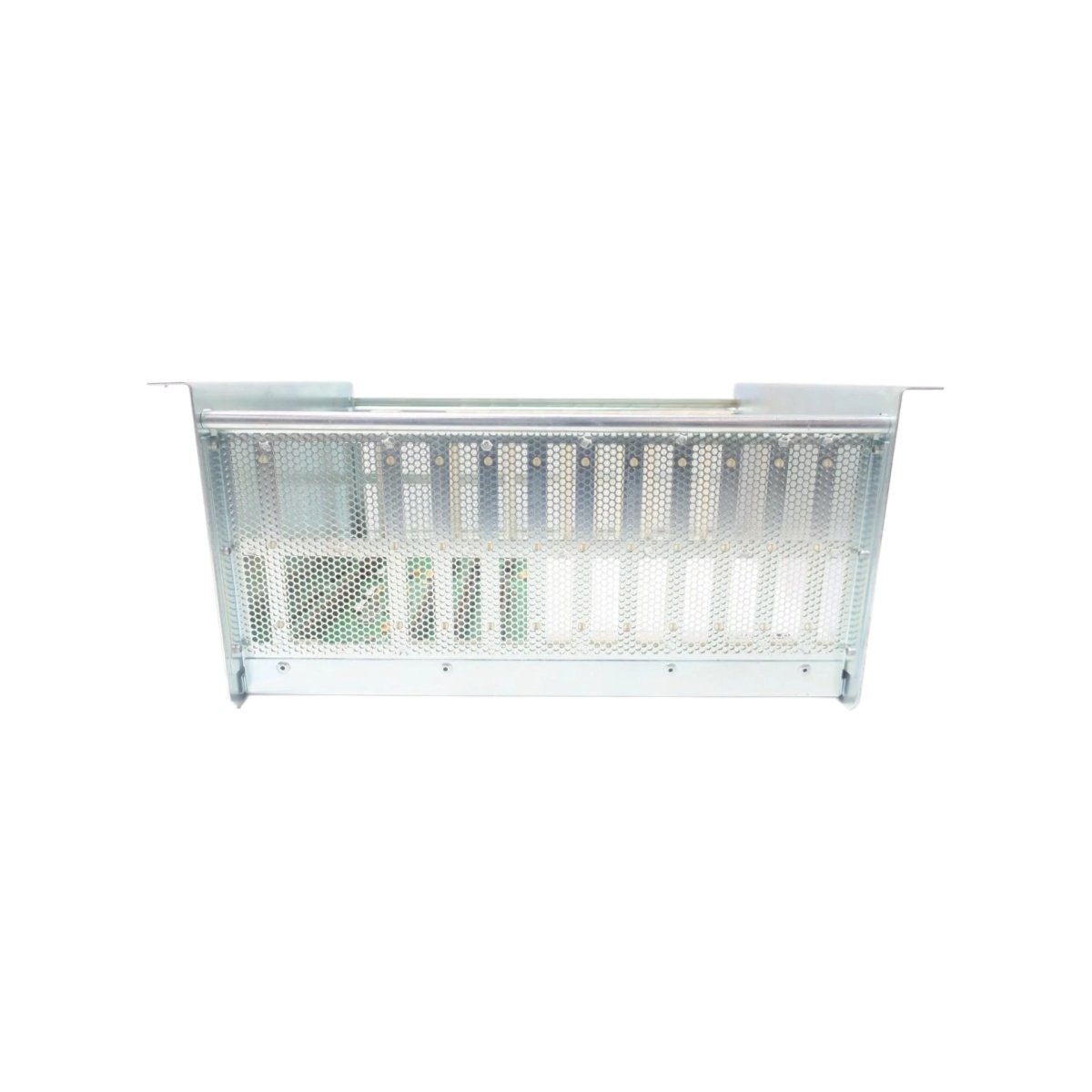
The 45C314 features twelve universal slots with keyed guides to prevent incorrect module insertion. Each slot uses a 96-pin DIN 41612 connector for signal and power distribution. The assembly’s cold-rolled steel housing provides excellent mechanical rigidity and EMI shielding. Its 1.5-millimeter thick panels resist flexing during module insertion and removal. The rack’s 6U height fits standard 19-inch cabinet configurations common in industrial settings.
Backplane Architecture and Power Distribution
The passive multilayer backplane distributes data, address, and control signals between modules. Separate power planes deliver 5 VDC, ±15 VDC, and 24 VDC to each slot individually. The bus structure supports 16-bit parallel communication for high-speed data exchange. Fuses on each voltage rail protect against short-circuit conditions. The backplane includes termination resistors for signal integrity on long bus lines.
Cooling and Thermal Management
Ventilation slots on the top and bottom panels promote natural convection airflow. The open design allows heat from modules to rise and escape without forced air. Adequate spacing between slots prevents thermal buildup from adjacent modules. The rack’s construction facilitates installation in cabinets with supplementary cooling. Users should maintain at least 50 mm clearance above and below for proper airflow.
Grounding and Shielding Provisions
A dedicated M6 chassis ground stud provides a low-impedance path to earth ground. Star grounding configuration minimizes ground loops between connected equipment. The steel enclosure attenuates electromagnetic interference from nearby devices. Shielded backplane traces reduce crosstalk between high-speed signal lines. The assembly meets industrial EMC standards for radiated and conducted emissions.
Installation and System Integration
Mounting ears on both sides secure the rack to standard 19-inch cabinet rails. The assembly’s depth of 200 millimeters accommodates most enclosure depths. A fully populated rack weighs approximately 10 kilograms, requiring sturdy rail support. Clear labeling identifies slot numbers and voltage test points on the backplane. The unit’s modular design allows future expansion without replacing the entire assembly.
Details
| Weight | 4.8 kg |
|---|---|
| Dimensions | 482.6 × 266.7 × 200 mm |
Reviews
There are no reviews yet.