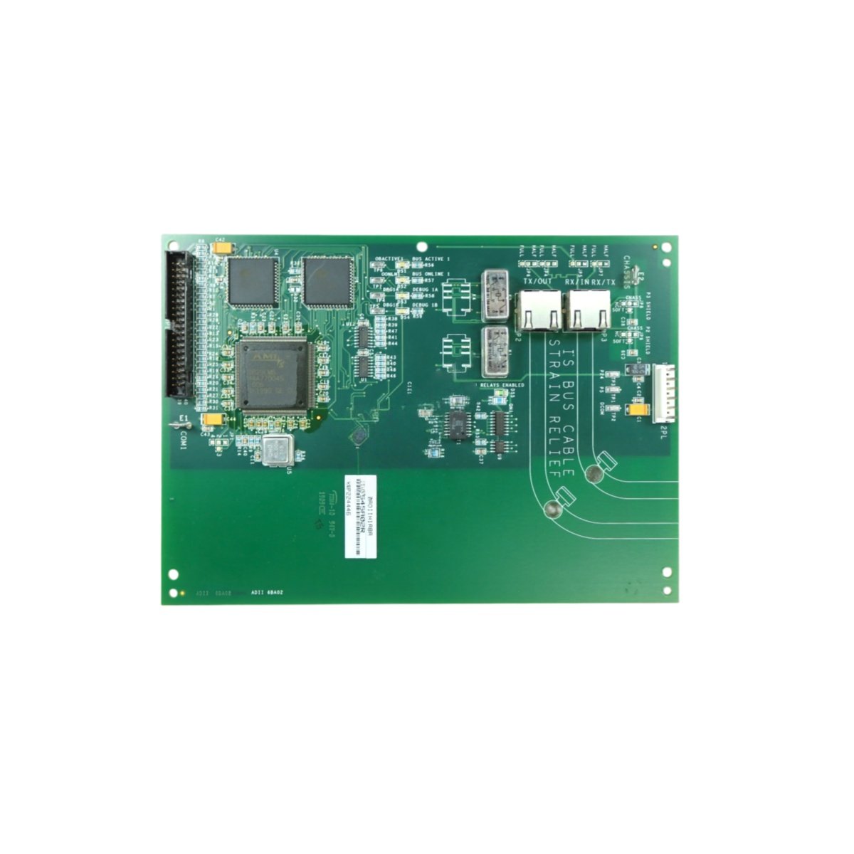
This turbine control LCI PCB manages load commutation inverter functions for GE Mark VIe systems. It controls starting and synchronization of large gas turbines. Therefore, it enables reliable turbine startup and grid synchronization for power generation.
Physical and Control Specifications
The GE IS200XDIAG1A IS200XDIAG1ADD measures 26.0 cm in length and 18.5 cm in width. Moreover, its board weight equals approximately 0.68 kg for rack mounting. A single 64-pin male connector links this board to the VME backplane. Additionally, the board integrates multiple LCI control and monitoring functions.
| Parameter | Specification |
|---|---|
| Brand | General Electric (GE) |
| Full Model | IS200XDIAG1A IS200XDIAG1ADD |
| Category | Turbine Control LCI PCB |
| Dimensions (L x W) | 26.0 cm x 18.5 cm (10.24″ x 7.28″) |
| Board Weight | 0.68 kg (1.50 lbs) |
| Primary Interface | 1 x 64-pin Male Connector |
| LCI Control Channels | 6 Independent Channels (3 Phase Pairs) |
| Output Signal Type | PWM (Pulse Width Modulated), 0-10 VDC |
| Switching Frequency | 2.5 kHz to 12 kHz (Software Configurable) |
| Synchronization Inputs | 3 Phase Voltage + 3 Phase Current |
| Speed Feedback Input | 2 Channels (Magnetic Pickup or Encoder) |
| Accuracy (Speed Control) | ±0.1% of Setpoint |
| Commutation Control | Natural + Forced |
| Startup Modes | Motor Start + Generator Start + Synchronous Condenser |
| On-Board Components | 1 DSP Processor + 1 FPGA + 6 Gate Driver ICs + 3 ADC Chips + 4 Memory Chips + 12 Protection Diodes + 1 Temperature Sensor + 2 Isolation Transformers + 1 Voltage Reference IC |
| Energy Storage | 6 x 100 µF Electrolytic Capacitors (100V) + 3 x 10 µF Tantalum (25V) |
| Operating Voltage | +5 VDC, +15 VDC, -15 VDC, and +24 VDC from Backplane |
| Isolation Rating | 2500 Vrms (Power to Control Circuits) |
| Operating Temperature | -20°C to +65°C (-4°F to +149°F) |
| Status Indicators | 6 Green LEDs (Channel Active) + 1 Green LED (Power) + 1 Red LED (Fault) + 3 Yellow LEDs (Phase Status) |
Load Commutation Inverter Control Features
The GE IS200XDIAG1A IS200XDIAG1ADD controls LCI functions for turbine starting. Specifically, the DSP processor executes commutation algorithms for synchronous motor starting. In addition, the board manages both motor start and generator start modes. Moreover, the FPGA handles high-speed PWM generation for thyristor firing. Furthermore, the module monitors three-phase voltage and current for synchronization. Consequently, this LCI PCB provides smooth turbine acceleration and grid connection.
PWM Output and Thyristor Gate Drive
Six PWM output channels provide control signals for LCI thyristor bridges. For instance, the switching frequency ranges from 2.5 kHz to 12 kHz. In addition, each channel drives optocouplers for firing high-power thyristors. Moreover, the board supports both natural and forced commutation modes. Furthermore, gate driver ICs provide isolation between control and power circuits. Thus, the GE IS200XDIAG1A IS200XDIAG1ADD reliably controls LCI starting of large gas turbines.
Speed Feedback and Synchronization
This LCI PCB accepts speed feedback from magnetic pickups or encoders. Specifically, two independent speed channels provide redundancy for critical applications. In addition, the speed control accuracy of ±0.1 percent ensures smooth acceleration. Moreover, phase voltage and current inputs synchronize the inverter with the grid. Furthermore, the module detects zero-crossing points for precise commutation timing. Therefore, this board enables seamless turbine-to-grid synchronization during startup.
Energy Storage and Control Stability
This turbine control LCI PCB stores energy using nine onboard capacitors for power filtering. Specifically, six high-voltage capacitors filter the power supplies for gate drivers. In addition, three tantalum capacitors provide high-frequency noise suppression for DSP circuits. Furthermore, these capacitors maintain PWM output stability during transient conditions. Moreover, the board includes a temperature sensor for derating protection. Thus, the GE IS200XDIAG1A IS200XDIAG1ADD ensures stable LCI control in demanding turbine environments.
Installation and Diagnostic Indicators
Eleven LED indicators provide operational status at a glance on this board. First, a green Power LED lights when the backplane supply voltages are present. Second, six green Channel Active LEDs illuminate when each PWM channel is enabled. Third, three yellow Phase Status LEDs show the condition of each phase feedback signal. Finally, a red Fault LED indicates overcurrent, overvoltage, or commutation failures. Additionally, the board features six mounting holes for secure rack attachment. Thus, you can monitor LCI control status instantly without external test equipment.
Details
| Weight | 0.1 kg |
|---|---|
| Dimensions | 25 × 108 × 127 mm |
Reviews
There are no reviews yet.