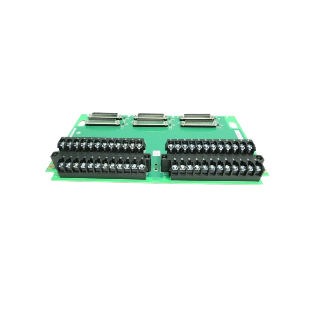
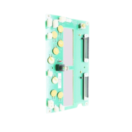
The GE IS200WETCH1A IS200WETCH1APR2 Printed Circuit Board provides discrete I/O interface for Mark VIe systems. This board connects field contact inputs and relay outputs to the turbine controller. You will find it in gas turbine and steam turbine protection applications. It accepts 24 VDC discrete signals from limit switches and pressure switches. Therefore, this unit handles critical turbine status monitoring functions.
The GE IS200WETCH1A IS200WETCH1APR2 Printed Circuit Board measures 230 mm in height and 155 mm in width. Its depth reaches 36 mm for chassis mounting. The unit weighs approximately 0.58 kilograms. It contains one 16-bit microcontroller and sixteen optocouplers. Two 50-pin ribbon headers provide I/O pack connections. Additionally, you get twelve status LEDs for diagnostics.
Key Technical Specifications
| Parameter | Value |
|---|---|
| Manufacturer | GE Energy / General Electric |
| Model | IS200WETCH1A / IS200WETCH1APR2 |
| Product Type | Printed Circuit Board |
| Discrete Inputs | 16 (24 VDC) |
| Discrete Outputs | 16 (relay, 2A) |
| Input Current | 7 mA per channel |
| Output Contact Rating | 2A at 30 VDC / 250 VAC |
| Microcontroller | 16-bit @ 40 MHz |
| Isolation Type | Optocoupler (1500 VAC) |
| Height | 230 mm |
| Width | 155 mm |
| Depth | 36 mm |
| Weight | 0.58 kg |
| Optocouplers | 16 |
| Status LEDs | 12 (PWR, COM, I/O) |
| Energy Storage | ≈ 300 µF (capacitive) |
| Power Consumption | 400 mA @ 5 VDC |
| Operating Temperature | -30°C to +65°C |
| Mounting Method | Chassis (4 screws) |
| Layer Count | 4-layer PCB |
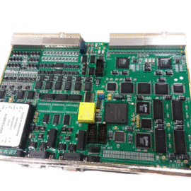
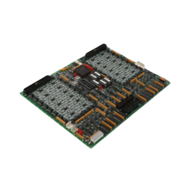
Internal Architecture and Energy Storage
The GE IS200WETCH1A IS200WETCH1APR2 Printed Circuit Board stores minimal energy in its power filter. Small electrolytic capacitors hold approximately 300 microfarads total capacitance. A 16-bit microcontroller scans all 16 inputs continuously at 10 ms intervals. This processor also controls the 16 relay outputs through driver transistors. Sixteen optocouplers isolate the input signals from the logic circuits. Each relay channel uses a mechanical relay with forced-guided contacts. The board includes a built-in watchdog timer for fail-safe operation. Twelve LEDs show power, communication, input, and output status clearly.
Connection Interfaces and Wiring Details
You will find two 50-pin ribbon cable headers on the board edge. Connect these headers to termination boards for field wiring. The GE IS200WETCH1A IS200WETCH1APR2 Printed Circuit Board also includes a 10-pin JTAG header. Use this header for firmware updates and debugging. Twelve LEDs indicate power, communication, and I/O status conditions. A green PWR LED lights up when the board receives 5 VDC. A yellow COM LED flashes during data exchange with the controller. Green LEDs above each input show active field signals. Red LEDs above each output show energized relay states.
Installation and Configuration Steps
You mount this board onto a metal chassis with four screws. First, drill four 4 mm holes matching the mounting pattern. Then, secure the board using M3 screws with standoffs. Connect the 5 VDC power wires to the terminal block. The GE IS200WETCH1A IS200WETCH1APR2 Printed Circuit Board consumes 400 mA from the supply. Connect the ribbon cables to the termination boards for all I/O signals. Use the Toolbox software to configure input filtering and output failsafe states. Set the board’s unique InSync address using the rotary switches. Download the configuration to the board’s flash memory. Verify that the green PWR LED remains steady after power-up. Test each input with a signal generator and each output with a continuity tester.
Details
| Weight | 0.1 kg |
|---|---|
| Dimensions | 25 × 108 × 127 mm |
Reviews
There are no reviews yet.