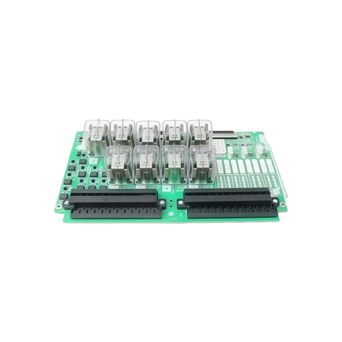
The GE IS200WEMAH1A IS200WEMAH1APR2 Printed Circuit Board manages analog I/O signals for Mark VIe systems. This board accepts voltage and current inputs from field transmitters. You will find it in gas turbine and steam turbine control applications. It provides high-precision measurement for pressure, flow, and level sensors. Therefore, this unit ensures accurate process monitoring for turbine operations.
The GE IS200WEMAH1A IS200WEMAH1APR2 Printed Circuit Board measures 235 mm in height and 158 mm in width. Its depth reaches 37 mm for chassis mounting. The unit weighs approximately 0.62 kilograms. It contains one 16-bit ADC and eight analog input channels. Three isolation amplifiers protect the controller circuits. Additionally, you get ten status LEDs for diagnostics.
Key Technical Specifications
| Parameter | Value |
|---|---|
| Manufacturer | GE Energy / General Electric |
| Model | IS200WEMAH1A / IS200WEMAH1APR2 |
| Product Type | Printed Circuit Board |
| Analog Inputs | 8 (differential) |
| Input Ranges | ±10 V, 0-10 V, 4-20 mA |
| ADC Resolution | 16 bits |
| Accuracy | ±0.1% of full scale |
| Input Impedance (V) | 100 k ohms |
| Input Impedance (mA) | 250 ohms |
| Update Rate | 20 ms per channel |
| Height | 235 mm |
| Width | 158 mm |
| Depth | 37 mm |
| Weight | 0.62 kg |
| ADC Count | 1 (16-bit) |
| Isolation Amplifiers | 3 |
| Status LEDs | 10 (PWR, COM, CH0-7) |
| Energy Storage | ≈ 350 µF (capacitive) |
| Power Consumption | 450 mA @ 5 VDC |
| Operating Temperature | -30°C to +65°C |
| Mounting Method | Chassis (4 screws) |
| Layer Count | 4-layer PCB |
Internal Architecture and Energy Storage
The GE IS200WEMAH1A IS200WEMAH1APR2 Printed Circuit Board stores minimal energy in its power filter. Small electrolytic capacitors hold approximately 350 microfarads total capacitance. A 16-bit successive approximation ADC converts each analog value with high precision. This ADC provides 65,536 discrete steps across the input range. Three isolation amplifiers separate the field signals from the logic circuits. A programmable gain amplifier adjusts input sensitivity for each channel. The board includes a precision voltage reference at 5.000 VDC. Ten LEDs show power, communication, and individual channel status clearly.
Connection Interfaces and Wiring Details
You will find two 50-pin ribbon cable headers on the board edge. Connect these headers to analog termination boards for field wiring. The GE IS200WEMAH1A IS200WEMAH1APR2 Printed Circuit Board also includes a 10-pin JTAG header. Use shielded twisted-pair cable for all analog signal connections. Ten LEDs indicate power, communication, and channel status conditions. A green PWR LED lights up when the board receives 5 VDC. A yellow COM LED flashes during data exchange with the controller. Green LEDs above each channel show active signal presence. A red FLT LED indicates an input over-range or open circuit condition.
Installation and Configuration Steps
You mount this board onto a metal chassis with four screws. First, drill four 4 mm holes matching the mounting pattern. Then, secure the board using M3 screws with standoffs. Connect the 5 VDC power wires to the terminal block. The GE IS200WEMAH1A IS200WEMAH1APR2 Printed Circuit Board consumes 450 mA from the supply. Connect the ribbon cables to the analog termination boards for all eight channels. Use the Toolbox software to configure each channel’s input range. Select voltage or current mode for each individual input. Set the scaling parameters to convert ADC counts to engineering units. Download the configuration to the board’s flash memory. Verify each channel with a precision signal calibrator before turbine startup.
Details
| Weight | 0.1 kg |
|---|---|
| Dimensions | 25 × 108 × 127 mm |

Reviews
There are no reviews yet.