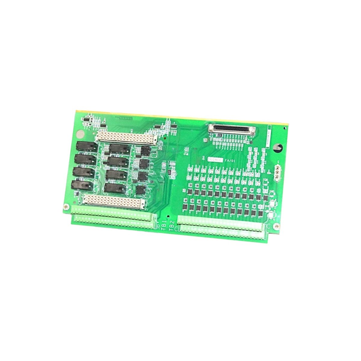
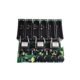
The GE IS200WDIIH3A IS200WDIIH3ABB Printed Circuit Board provides digital I/O expansion for Mark VIe systems. This board interfaces field devices with the turbine controller. You will find it in gas turbine and steam turbine control cabinets. It handles both input and output signals for valve position feedback. Therefore, this unit ensures reliable turbine operation under harsh conditions.
The GE IS200WDIIH3A IS200WDIIH3ABB Printed Circuit Board measures 225 mm in height and 152 mm in width. Its depth reaches 36 mm for chassis mounting. The unit weighs approximately 0.55 kilograms. It contains one 16-bit microcontroller and twenty-four optocouplers. Two 50-pin ribbon headers provide I/O pack connections. Additionally, you get fourteen status LEDs for diagnostics.
Key Technical Specifications
| Parameter | Value |
|---|---|
| Manufacturer | GE Energy / General Electric |
| Model | IS200WDIIH3A / IS200WDIIH3ABB |
| Product Type | Printed Circuit Board |
| Digital Inputs | 12 (24 VDC) |
| Digital Outputs | 12 (sourcing, 0.5A) |
| Input Current | 8 mA per channel |
| Output Current | 0.5 A per channel |
| Isolation Type | Optocoupler (1500 VAC) |
| Microcontroller | 16-bit @ 40 MHz |
| Height | 225 mm |
| Width | 152 mm |
| Depth | 36 mm |
| Weight | 0.55 kg |
| Optocouplers | 24 |
| Status LEDs | 14 (PWR, COM, I/O) |
| Energy Storage | ≈ 280 µF (capacitive) |
| Power Consumption | 380 mA @ 5 VDC |
| Operating Temperature | -30°C to +65°C |
| Mounting Method | Chassis (4 screws) |
| Layer Count | 6-layer PCB |
Internal Architecture and Energy Storage
The GE IS200WDIIH3A IS200WDIIH3ABB Printed Circuit Board stores minimal energy in its power filter. Small electrolytic capacitors hold approximately 280 microfarads total capacitance. A 16-bit microcontroller scans all 12 inputs at 5 ms intervals. This processor also controls the 12 sourcing output transistors. Twenty-four optocouplers isolate both inputs and outputs from the logic circuits. Each output channel uses a power MOSFET switching device. The board includes a hardware watchdog timer for fail-safe operation. Fourteen LEDs show power, communication, input, and output status clearly.
Connection Interfaces and Wiring Details
You will find two 50-pin ribbon cable headers on the board edge. Connect these headers to termination boards for field wiring. The GE IS200WDIIH3A IS200WDIIH3ABB Printed Circuit Board also includes a 10-pin JTAG header. Use this header for firmware updates and debugging purposes. Fourteen LEDs indicate power, communication, and individual I/O status. A green PWR LED lights up when the board receives 5 VDC. A yellow COM LED flashes during data exchange with the controller. Green LEDs above each input show active field signals. Yellow LEDs above each output show commanded-on status.
Installation and Configuration Steps
You mount this board onto a metal chassis with four screws. First, drill four 4 mm holes matching the mounting pattern. Then, secure the board using M3 screws with standoffs. Connect the 5 VDC power wires to the terminal block. The GE IS200WDIIH3A IS200WDIIH3ABB Printed Circuit Board consumes 380 mA from the supply. Connect the ribbon cables to the termination boards for all I/O signals. Use the Toolbox software to configure input filtering and output failsafe states. Set the board’s unique InSync address using the rotary switches. Download the configuration to the board’s non-volatile memory. Verify that the green PWR LED remains steady after power-up. Test each input with a signal generator and each output with a load.
Details
| Weight | 0.1 kg |
|---|---|
| Dimensions | 25 × 108 × 127 mm |
Reviews
There are no reviews yet.