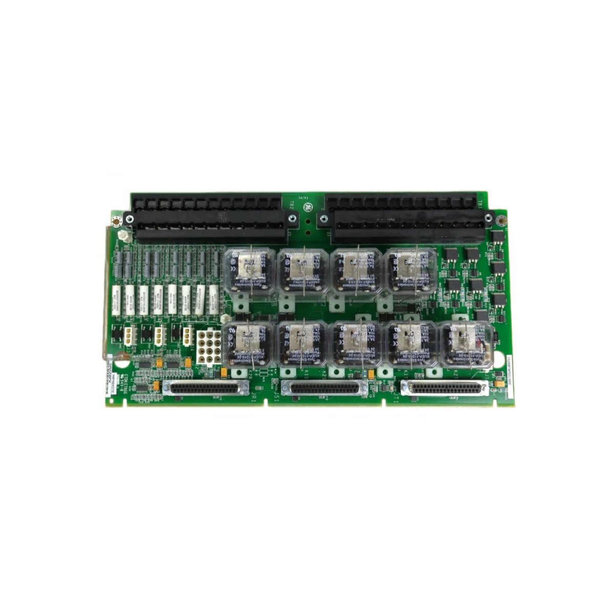
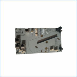
The GE IS200VVIBH1C IS200VVIBH1CAC VME Vibration Card monitors turbine shaft vibrations for Mark VIe systems. This card accepts accelerometer and proximity probe inputs. You will find it in gas turbine and steam turbine protection applications. It detects bearing wear, unbalance, and misalignment conditions early. Therefore, this unit prevents catastrophic turbine damage from excessive vibration.
The GE IS200VVIBH1C IS200VVIBH1CAC VME Vibration Card measures 233 mm in height and 160 mm in width. Its depth reaches 40 mm for VME chassis mounting. The unit weighs approximately 0.72 kilograms. It contains one 32-bit DSP and eight vibration input channels. Four analog outputs provide 4-20 mA signals for external monitoring. Additionally, you get twelve status LEDs for diagnostics.
Key Technical Specifications
| Parameter | Value |
|---|---|
| Manufacturer | GE Energy / General Electric |
| Model | IS200VVIBH1C / IS200VVIBH1CAC |
| Product Type | VME Vibration Card |
| Vibration Inputs | 8 (differential) |
| Sensor Types | Accelerometer, proximity probe |
| Input Range | ±25 V peak |
| ADC Resolution | 16 bits |
| Sampling Rate | 10 kHz per channel |
| Analog Outputs | 4 (4-20 mA) |
| Processor | 32-bit DSP @ 100 MHz |
| Height | 233 mm |
| Width | 160 mm |
| Depth | 40 mm |
| Weight | 0.72 kg |
| Status LEDs | 12 (PWR, COM, CH0-7) |
| Energy Storage | ≈ 400 µF (capacitive) |
| Power Consumption | 500 mA @ 5 VDC |
| Operating Temperature | -30°C to +65°C |
| Mounting Method | VME chassis (inject/eject) |
| Bus Interface | VME P1/P2 connectors |
Internal Architecture and Energy Storage
The GE IS200VVIBH1C IS200VVIBH1CAC VME Vibration Card stores moderate energy in its power filter. Electrolytic capacitors hold approximately 400 microfarads total capacitance. A 32-bit DSP runs vibration analysis algorithms at 100 MHz. This processor performs FFT calculations for frequency domain analysis. Eight independent input channels sample simultaneously at 10 kHz. Four 16-bit DACs convert processed data to 4-20 mA output signals. The card includes programmable filters for each input channel. Twelve LEDs show power, communication, and channel status clearly.
Connection Interfaces and Wiring Details
You will find a 50-pin front panel connector for field wiring. Connect this to a termination board for vibration sensor inputs. The GE IS200VVIBH1C IS200VVIBH1CAC VME Vibration Card also uses VME P1 and P2 backplane connectors. Use shielded twisted-pair cable for all vibration signal connections. Twelve LEDs indicate power, communication, and channel status conditions. A green PWR LED lights up when the card receives 5 VDC. A yellow COM LED flashes during data exchange with the controller. Green LEDs above each channel show active signal presence. A red FLT LED indicates a sensor or wiring fault.
Configuration and Installation Steps
You slide this VME card into a standard 6U VME chassis. First, align the card with the upper and lower card guides. Then, push it firmly until the backplane connectors seat completely. Use the injector/ejector handles to seat the card properly. The GE IS200VVIBH1C IS200VVIBH1CAC VME Vibration Card requires 5 VDC from the VME backplane. Use the Toolbox software to configure each vibration channel. Select the sensor type (accelerometer or proximity probe). Set the scaling parameters for engineering units (mm/s or mils). Configure the FFT parameters including lines of resolution and frequency range. Download the configuration to the card’s flash memory. Verify each channel with a vibration calibrator before turbine startup.
Details
| Weight | 0.1 kg |
|---|---|
| Dimensions | 25 × 108 × 127 mm |
Reviews
There are no reviews yet.