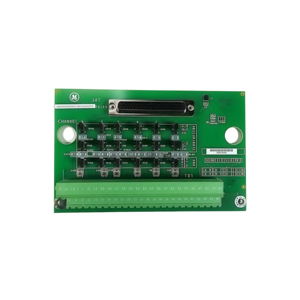
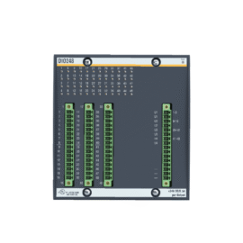
The GE IS200VTCCH1C IS200VTCCH1CBD Printed Circuit Board provides thermocouple temperature monitoring for Mark VIe systems. This board accepts up to eight thermocouple inputs for exhaust gas measurement. You will find it in gas turbine and steam turbine control cabinets. It delivers high-accuracy readings for blade path temperature monitoring. Therefore, this unit protects turbine components from thermal overload conditions.
The GE IS200VTCCH1C IS200VTCCH1CBD Printed Circuit Board measures 238 mm in height and 162 mm in width. Its depth reaches 39 mm for chassis mounting. The unit weighs approximately 0.68 kilograms. It contains one 18-bit ADC and eight thermocouple input channels. One onboard temperature sensor provides cold junction compensation. Additionally, you get twelve status LEDs for diagnostics.
Key Technical Specifications
| Parameter | Value |
|---|---|
| Manufacturer | GE Energy / General Electric |
| Model | IS200VTCCH1C / IS200VTCCH1CBD |
| Product Type | Printed Circuit Board |
| Thermocouple Inputs | 8 (type J, K, T, E, N, S) |
| Temperature Range | -200°C to +1300°C (type dependant) |
| ADC Resolution | 18 bits |
| Accuracy | ±0.5°C typical |
| Cold Junction Compensation | Automatic (onboard sensor) |
| Update Rate | 50 ms per channel |
| Height | 238 mm |
| Width | 162 mm |
| Depth | 39 mm |
| Weight | 0.68 kg |
| Isolation Voltage | 1500 VAC (channel to bus) |
| Status LEDs | 12 (PWR, COM, CH0-7) |
| Energy Storage | ≈ 320 µF (capacitive) |
| Power Consumption | 300 mA @ 5 VDC |
| Operating Temperature | -30°C to +65°C |
| Mounting Method | Chassis (4 screws) |
| Layer Count | 4-layer PCB |
Internal Architecture and Energy Storage
The GE IS200VTCCH1C IS200VTCCH1CBD Printed Circuit Board stores minimal energy in its power filter. Small electrolytic capacitors hold approximately 320 microfarads total capacitance. An 18-bit delta-sigma ADC provides high-resolution temperature measurement. This ADC eliminates the need for external signal conditioning circuits. An onboard semiconductor sensor measures the cold junction temperature accurately. The board automatically compensates each thermocouple reading using this value. A precision voltage reference at 2.5 VDC ensures measurement stability. Twelve LEDs show power, communication, and individual channel status clearly.
Connection Interfaces and Wiring Details
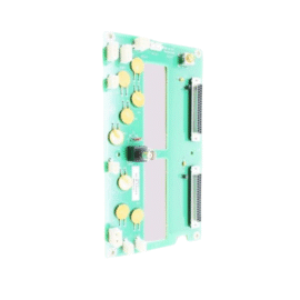
You will find two 50-pin ribbon cable headers on the board edge. Connect these headers to termination boards for thermocouple wiring. The GE IS200VTCCH1C IS200VTCCH1CBD Printed Circuit Board also includes a 10-pin JTAG header. Use extension-grade thermocouple wire for all field connections. Connect the positive thermocouple lead to the + terminal. Connect the negative lead to the – terminal. Twelve LEDs indicate power, communication, and channel status conditions. A green PWR LED lights up when the board receives 5 VDC. A yellow COM LED flashes during data exchange with the controller. Green LEDs above each channel show active signal presence. A red FLT LED indicates an open thermocouple or wiring fault.
Installation and Configuration Steps
You mount this board onto a metal chassis with four screws. First, drill four 4 mm holes matching the mounting pattern. Then, secure the board using M3 screws with standoffs. Connect the 5 VDC power wires to the terminal block. The GE IS200VTCCH1C IS200VTCCH1CBD Printed Circuit Board consumes 300 mA from the supply. Connect the ribbon cables to the termination boards for all eight channels. Use the Toolbox software to configure each channel’s thermocouple type. Select the correct type (J, K, T, E, N, or S) for each input. Set the temperature units to Celsius or Fahrenheit. Download the configuration to the board’s non-volatile memory. Verify each channel with a thermocouple simulator before turbine startup.
Details
| Weight | 0.1 kg |
|---|---|
| Dimensions | 25 × 108 × 127 mm |
Reviews
There are no reviews yet.