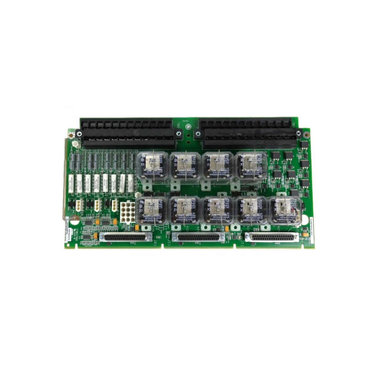
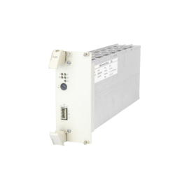
The GE IS200VSVOH1A IS200VSVOH1AMR Printed Circuit Board controls servo valve positioning for Mark VIe systems. This board drives hydraulic actuators for turbine fuel and steam control. You will find it in gas turbine and steam turbine control cabinets. It provides proportional current outputs to servo valve coils. Therefore, this unit ensures precise fuel flow and valve position regulation.
The GE IS200VSVOH1A IS200VSVOH1AMR Printed Circuit Board measures 245 mm in height and 168 mm in width. Its depth reaches 40 mm for chassis mounting. The unit weighs approximately 0.82 kilograms. It contains one 32-bit DSP and four servo output channels. Sixteen analog inputs provide position feedback from LVDT sensors. Additionally, you get twelve status LEDs for diagnostics.
Key Technical Specifications
| Parameter | Value |
|---|---|
| Manufacturer | GE Energy / General Electric |
| Model | IS200VSVOH1A / IS200VSVOH1AMR |
| Product Type | Printed Circuit Board |
| Servo Outputs | 4 (4-20 mA or ±10 V) |
| Output Current | 20 mA maximum per channel |
| Analog Inputs | 16 (LVDT position feedback) |
| ADC Resolution | 16 bits |
| DAC Resolution | 16 bits |
| Processor | 32-bit DSP @ 100 MHz |
| Height | 245 mm |
| Width | 168 mm |
| Depth | 40 mm |
| Weight | 0.82 kg |
| Status LEDs | 12 (PWR, COM, VALVE) |
| Energy Storage | ≈ 520 µF (capacitive) |
| Power Consumption | 650 mA @ 5 VDC |
| Operating Temperature | -30°C to +65°C |
| Mounting Method | Chassis (6 screws) |
| Layer Count | 6-layer PCB |
Internal Architecture and Energy Storage
The GE IS200VSVOH1A IS200VSVOH1AMR Printed Circuit Board stores moderate energy in its power filter. Electrolytic capacitors hold approximately 520 microfarads total capacitance. A 32-bit DSP runs servo control algorithms at 100 MHz. This processor includes PID loops for closed-loop valve positioning. Four 16-bit DACs convert digital commands to analog output signals. Sixteen 16-bit ADCs read LVDT position feedback from the valves. Each servo channel uses independent hardware fault detection circuits. Twelve LEDs show power, communication, and individual valve status clearly.
Connection Interfaces and Wiring Details
You will find two 50-pin ribbon cable headers on the board edge. Connect these headers to termination boards for field wiring. The GE IS200VSVOH1A IS200VSVOH1AMR Printed Circuit Board also includes a 10-pin JTAG header. Use shielded twisted-pair cable for all LVDT and servo connections. Connect the servo output wires to the appropriate termination board terminals. Connect the LVDT primary and secondary wires to the analog input channels. Twelve LEDs indicate power, communication, and valve status conditions. A green PWR LED lights up when the board receives 5 VDC. A yellow COM LED flashes during data exchange with the controller. Green LEDs above each channel show active valve control.
Installation and Configuration Steps
You mount this board onto a metal chassis with six screws. First, drill six 5 mm holes matching the mounting pattern. Then, secure the board using M4 screws with lock washers. Connect the 5 VDC and 24 VDC power wires to the terminal blocks. The GE IS200VSVOH1A IS200VSVOH1AMR Printed Circuit Board consumes 650 mA from the 5 VDC supply. Connect the ribbon cables to the termination boards for all channels. Use the Toolbox software to configure each servo channel’s parameters. Set the output range (4-20 mA or ±10 V) for each valve. Configure the LVDT excitation frequency and voltage. Tune the PID gains for stable valve response. Download the configuration to the board’s flash memory. Test each servo channel with a valve simulator before field installation.
Details
| Weight | 0.1 kg |
|---|---|
| Dimensions | 25 × 108 × 127 mm |
Reviews
There are no reviews yet.