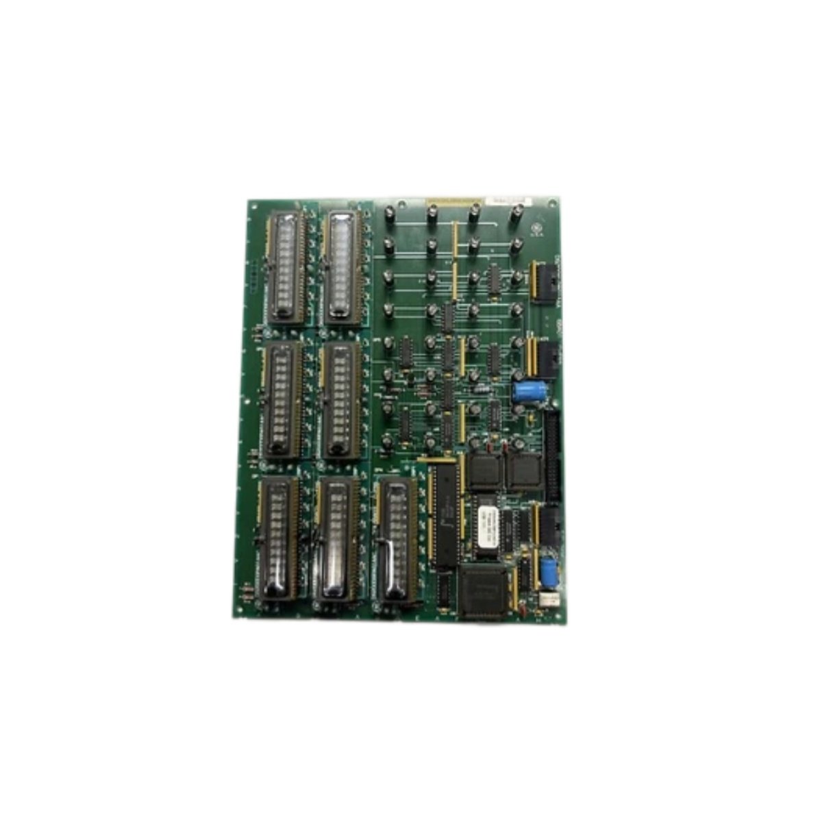
The GE IS200VPWRH1A IS200VPWRH1AGC Printed Circuit Board provides power supply management for Mark VIe systems. This board distributes DC power to all I/O packs and control cards. You will find it in gas turbine and steam turbine control cabinets. It monitors voltage levels and current draw for system protection. Therefore, this unit ensures stable power delivery under all operating conditions.
The GE IS200VPWRH1A IS200VPWRH1AGC Printed Circuit Board measures 230 mm in height and 155 mm in width. Its depth reaches 35 mm for chassis mounting. The unit weighs approximately 0.58 kilograms. It contains one 16-bit microcontroller and four DC-DC converters. Six voltage monitor circuits protect against overvoltage conditions. Additionally, you get ten status LEDs for diagnostics.
Key Technical Specifications
| Parameter | Value |
|---|---|
| Manufacturer | GE Energy / General Electric |
| Model | IS200VPWRH1A / IS200VPWRH1AGC |
| Product Type | Printed Circuit Board |
| Input Voltage | 24 VDC nominal (18-32 VDC) |
| Output Voltages | 5 VDC, ±15 VDC, 24 VDC |
| Total Output Power | 150 W |
| Efficiency | 88% typical |
| DC-DC Converters | 4 (isolated) |
| Voltage Monitors | 6 (over/under) |
| Microcontroller | 16-bit @ 40 MHz |
| Height | 230 mm |
| Width | 155 mm |
| Depth | 35 mm |
| Weight | 0.58 kg |
| Status LEDs | 10 (PWR, OUT, FLT) |
| Energy Storage | ≈ 600 µF (capacitive) |
| Power Consumption | 50 mA (quiescent) |
| Operating Temperature | -30°C to +65°C |
| Mounting Method | Chassis (4 screws) |
| Layer Count | 4-layer PCB |
Internal Architecture and Energy Storage
The GE IS200VPWRH1A IS200VPWRH1AGC Printed Circuit Board stores moderate energy in its input filter. Electrolytic capacitors hold approximately 600 microfarads total capacitance. Four isolated DC-DC converters generate all necessary system voltages. Each converter provides short circuit and overcurrent protection. Six voltage monitor circuits continuously check each output rail. A 16-bit microcontroller logs voltage events and reports faults. The board includes reverse polarity protection on the 24 VDC input. Ten LEDs show input power, output status, and fault conditions clearly.
Connection Interfaces and Wiring Details
You will find two 50-pin ribbon cable headers on the board edge. Connect these headers to backplane distribution boards. The GE IS200VPWRH1A IS200VPWRH1AGC Printed Circuit Board also includes a 10-pin JTAG header. Use 14 AWG wire for the 24 VDC input connection. Connect the positive wire to the +24V terminal and negative to COM. Ten LEDs indicate input power, output status, and fault conditions. A green PWR LED lights up when the board receives 24 VDC. Green LEDs for each output show presence of +5 V, +15 V, -15 V, and 24 VDC. A red FLT LED indicates an overcurrent or overvoltage shutdown condition on any output.
Installation and Configuration Steps
You mount this board onto a metal chassis with four screws. First, drill four 4 mm holes matching the mounting pattern. Then, secure the board using M3 screws with standoffs. Connect the 24 VDC input wires to the terminal block. The GE IS200VPWRH1A IS200VPWRH1AGC Printed Circuit Board consumes 50 mA in standby mode. Connect the ribbon cables to the backplane distribution boards. Use the Toolbox software to configure voltage alarm thresholds. Set the overvoltage and undervoltage trip points for each output. Enable or disable individual output channels as needed. Download the configuration to the board’s non-volatile memory. Verify each output voltage with a multimeter before connecting loads. Monitor the status LEDs during initial power-up for any faults.
Details
| Weight | 0.1 kg |
|---|---|
| Dimensions | 25 × 108 × 127 mm |
Reviews
There are no reviews yet.