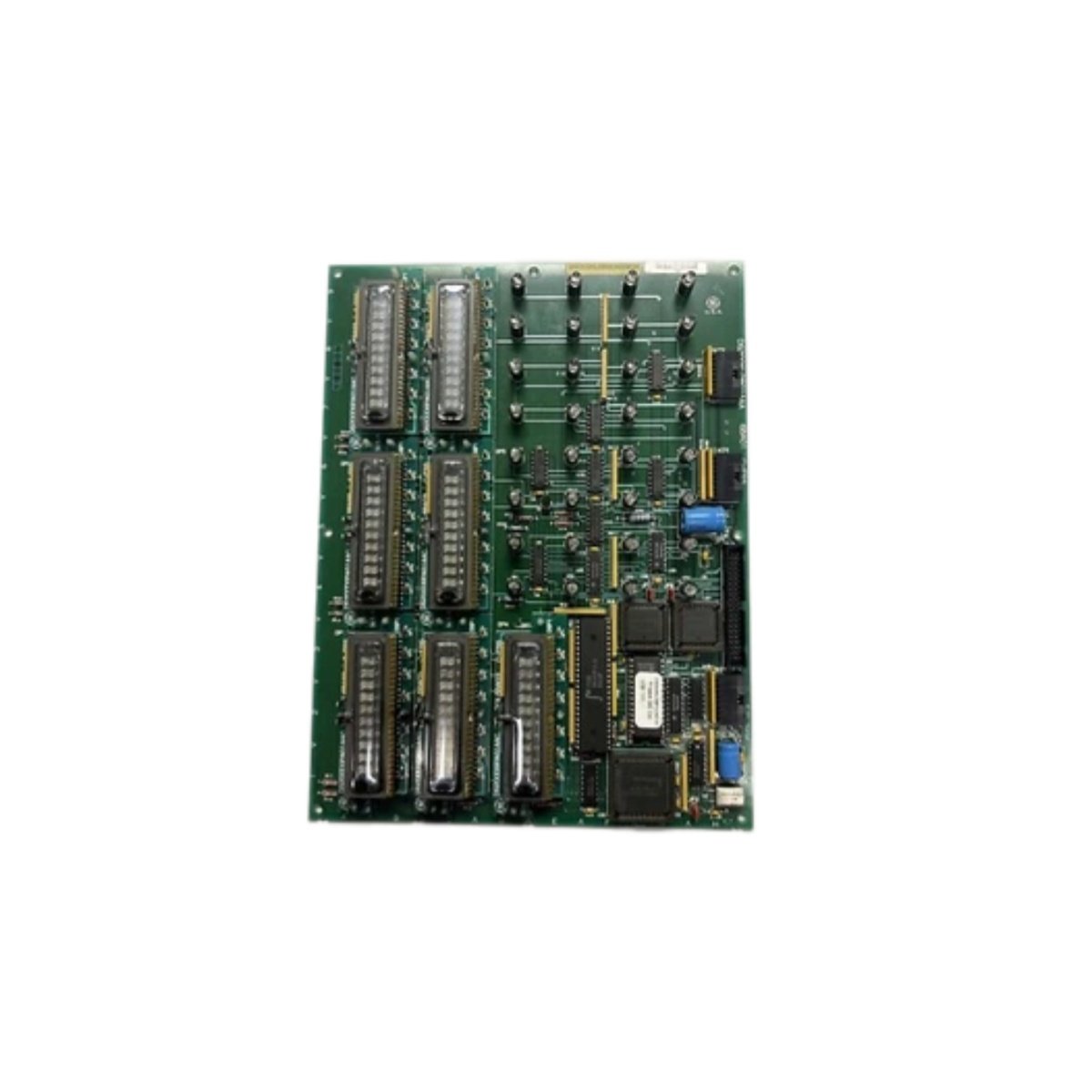
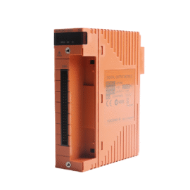
The GE IS200VPROH1B IS200VPROH1BCA Protection Card provides redundant safety monitoring for Mark VIe systems. This card oversees turbine overspeed and over-temperature conditions continuously. You will find it in gas turbine and steam turbine control cabinets. It uses hardware-based voting logic for fail-safe emergency shutdowns. Therefore, this unit meets SIL 3 safety integrity level requirements.
The GE IS200VPROH1B IS200VPROH1BCA Protection Card measures 240 mm in height and 160 mm in width. Its depth reaches 42 mm for chassis mounting. The unit weighs approximately 0.78 kilograms. It contains one 32-bit processor and three independent speed comparators. Sixteen discrete inputs accept 24 VDC signals from safety devices. Additionally, you get fourteen status LEDs for diagnostics.
Key Technical Specifications
| Parameter | Value |
|---|---|
| Manufacturer | GE Energy / General Electric |
| Model | IS200VPROH1B / IS200VPROH1BCA |
| Product Type | Protection Card |
| Safety Rating | SIL 3 (IEC 61508) |
| Speed Inputs | 3 (magnetic pickup) |
| Speed Range | 0 to 55,000 RPM |
| Overspeed Detection | 3 hardware comparators |
| Temperature Inputs | 4 (thermocouple) |
| Discrete Inputs | 16 (24 VDC) |
| Relay Outputs | 4 (2A, safety-rated) |
| Processor | 32-bit @ 100 MHz |
| Height | 240 mm |
| Width | 160 mm |
| Depth | 42 mm |
| Weight | 0.78 kg |
| Status LEDs | 14 (PWR, RUN, TRIP) |
| Energy Storage | ≈ 500 µF (capacitive) |
| Power Consumption | 550 mA @ 5 VDC |
| Operating Temperature | -30°C to +65°C |
| Mounting Method | Chassis (6 screws) |
| Diagnostic Coverage | 99.9% |
Internal Architecture and Energy Storage
The GE IS200VPROH1B IS200VPROH1BCA Protection Card stores moderate energy in its power filter. Electrolytic capacitors hold approximately 500 microfarads total capacitance. A 32-bit processor runs safety logic at 100 MHz with error checking. Three independent hardware comparators monitor each speed channel continuously. These comparators trigger directly without software intervention for SIL compliance. Four thermocouple inputs provide gas temperature monitoring for over-temperature protection. Sixteen optocouplers isolate the discrete inputs from the processor. Four safety-rated relay outputs provide redundant shutdown contacts. Fourteen LEDs show power, run, trip, and channel status clearly.
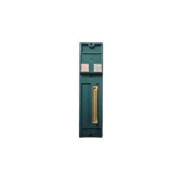
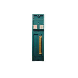
Connection Interfaces and Wiring Details
You will find two 50-pin ribbon cable headers on the board edge. Connect these headers to termination boards for field wiring. The GE IS200VPROH1B IS200VPROH1BCA Protection Card also includes a 10-pin JTAG header. Use shielded twisted-pair cable for all speed sensor and thermocouple connections. Connect each magnetic pickup to its dedicated speed input channel. Connect thermocouple wires to the temperature input terminals. Fourteen LEDs indicate power, run, trip, and status conditions. A green PWR LED lights up when the card receives 5 VDC. A green RUN LED flashes when the processor executes logic normally. A red TRIP LED indicates an overspeed or over-temperature condition.
Configuration and Installation Steps
You mount this card onto a metal chassis with six screws. First, drill six 5 mm holes matching the mounting pattern. Then, secure the card using M4 screws with lock washers. Connect the 5 VDC and 24 VDC power wires to the terminal blocks. The GE IS200VPROH1B IS200VPROH1BCA Protection Card consumes 550 mA from the 5 VDC supply. Connect the ribbon cables to the termination boards for all signals. Use the Toolbox software to configure overspeed and over-temperature setpoints. Set the number of speed sensor teeth for each pickup. Configure the voting logic (2-out-of-3) for tripping. Program the relay mapping for emergency shutdown valves. Download the configuration to the card’s flash memory. Test each protection channel with a pulse generator and temperature simulator before turbine startup.
Details
| Weight | 0.1 kg |
|---|---|
| Dimensions | 25 × 108 × 127 mm |
Reviews
There are no reviews yet.