The GE IS200TVBAH2A IS200TVBAH2AAA modulator board generates pulse signals for turbine control systems. This board converts DC voltage commands into variable frequency outputs. You will find this unit inside a standard Mark VI Speedtronic rack. It drives external actuators and positioning devices with precision.
Technical Specifications
The table below lists accurate parameters for this modulator board.
| Parameter | Specification |
|---|---|
| Full Product Model | GE IS200TVBAH2A IS200TVBAH2AAA |
| Category | Modulator Board |
| Width | 3.5 inches (88.9 mm) |
| Height | 9.5 inches (241.3 mm) |
| Weight | 0.59 kg (1.30 lbs) |
| Output Channels | 2 independent modulator channels |
| Frequency Range | 0 to 25 kHz per channel |
| Output Voltage | 0 to 10 V DC, 0 to 24 V DC |
| Onboard Components | 1 modulator IC, 4 transistors, 8 capacitors |
| Connector Interfaces | 2 backplane connectors (P1, P2), 1 output header |
| Energy Storage | 2 capacitors (470 µF each) |
| Operating Voltage | 5 V DC from backplane supply |
| Power Consumption | 14 W typical |
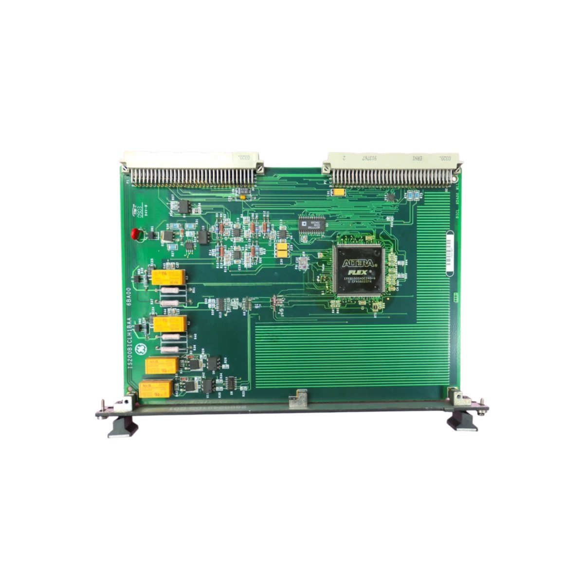
Physical Layout and Component Arrangement
The GE IS200TVBAH2A IS200TVBAH2AAA modulator board uses a rigid epoxy substrate. One primary modulator IC sits at the center of this board. Four power transistors surround the IC for signal amplification. Eight ceramic capacitors provide high-frequency noise filtering. Two backplane connectors anchor this board securely into the Mark VI rack. A dedicated output header connects to external field devices.
Functional Features and Integration
This modulator board converts analog setpoints into proportional pulse trains. It generates square wave signals at programmable frequencies and duty cycles. The GE IS200TVBAH2A IS200TVBAH2AAA also includes short-circuit protection on each output channel. Consequently, it ensures reliable operation even under fault conditions.
Installation and Safe Handling
Always power down the rack before inserting this modulator board. Hold the GE IS200TVBAH2A IS200TVBAH2AAA firmly by its non-conductive edges. Push the board straight down until both backplane connectors lock into place. Then connect the output header to your field wiring harness. After installation, verify output signals through the Mark VI diagnostic software.
Details
| Weight | 0.1 kg |
|---|---|
| Dimensions | 25 × 108 × 127 mm |
Reviews
There are no reviews yet.