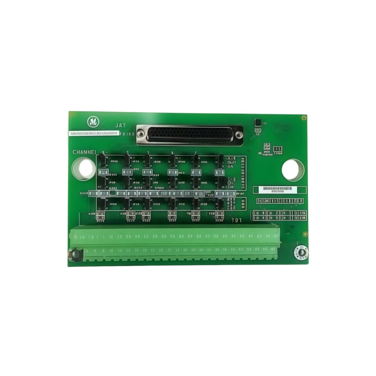
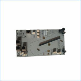
The GE IS200TRTDH1C IS200TRTDH1CCC RTD Input Terminal Board provides RTD sensor termination for Mark VIe systems. This board connects resistance temperature detectors to the I/O pack. You will find it in gas turbine and steam turbine control cabinets. It accepts up to eight 3-wire RTD inputs for temperature monitoring. Therefore, this unit simplifies field wiring for thermal measurement applications.
The GE IS200TRTDH1C IS200TRTDH1CCC RTD Input Terminal Board measures 215 mm in height and 140 mm in width. Its depth reaches 28 mm for DIN rail mounting. The unit weighs approximately 0.42 kilograms. It contains no active electronic components at all. Twenty-four screw terminals accept RTD and shield connections. Additionally, you get two 50-pin ribbon headers for I/O pack connection.
Key Technical Specifications
| Parameter | Value |
|---|---|
| Manufacturer | GE Energy / General Electric |
| Model | IS200TRTDH1C / IS200TRTDH1CCC |
| Product Type | RTD Input Terminal Board |
| RTD Channels | 8 (3-wire configuration) |
| RTD Types | Pt100, Ni100, Cu10 |
| Terminal Count | 24 (screw type) |
| Wire Gauge Range | 24 to 16 AWG |
| I/O Pack Connector | 2 x 50-pin ribbon header |
| Height | 215 mm |
| Width | 140 mm |
| Depth | 28 mm |
| Weight | 0.42 kg |
| Internal Components | 0 (fully passive) |
| Energy Storage | 0 Joules (none) |
| Mounting Type | 35 mm DIN rail |
| PCB Layer Count | 4-layer |
| Operating Temperature | -30°C to +65°C |
| Terminal Pitch | 5.5 mm spacing |
Internal Architecture and Energy Storage
The GE IS200TRTDH1C IS200TRTDH1CCC RTD Input Terminal Board stores absolutely no electrical energy internally. It contains no capacitors, batteries, or semiconductor devices. Twenty-four screw terminals connect directly to two 50-pin ribbon headers through copper traces. Each RTD channel uses three terminals: excitation, sense A, and sense B. The PCB uses a 4-layer construction for noise reduction on low-level signals. A metal DIN rail clip provides secure mounting and chassis grounding. The board includes a dedicated ground terminal for shield drain wires. Each terminal has a test point for probe access during troubleshooting.
Connection Interfaces and Wiring Details
You will find 24 screw terminals arranged for eight RTD channels. Each RTD requires three terminals: EXC, SENSE, and RETURN. Connect the RTD positive lead to the EXC terminal. Use 16 to 24 AWG copper wire for all RTD connections. The GE IS200TRTDH1C IS200TRTDH1CCC RTD Input Terminal Board includes two 50-pin female headers on the PCB. Connect one header to the I/O pack using a shielded ribbon cable. Connect the second header to another terminal board for daisy-chaining if needed. Use shielded twisted-pair cable for RTD runs longer than 10 meters.
Installation and Mounting Steps
You mount this terminal board onto standard 35 mm DIN rail. First, hook the top clip onto the rail edge securely. Then, press the bottom toward the rail until it snaps into place. Slide the board along the rail for easy panel layout. Connect all RTD wiring before attaching the I/O pack. The GE IS200TRTDH1C IS200TRTDH1CCC RTD Input Terminal Board requires no external power supply. It simply routes RTD signals between field sensors and the I/O pack. For high-vibration areas, add end stops on both rail ends. Label each terminal with its corresponding channel and wire function clearly. Connect the ribbon cable between the terminal board and the RTD I/O pack. Test each RTD connection with a resistance meter before system startup.
Details
| Weight | 0.1 kg |
|---|---|
| Dimensions | 25 × 108 × 127 mm |
Reviews
There are no reviews yet.