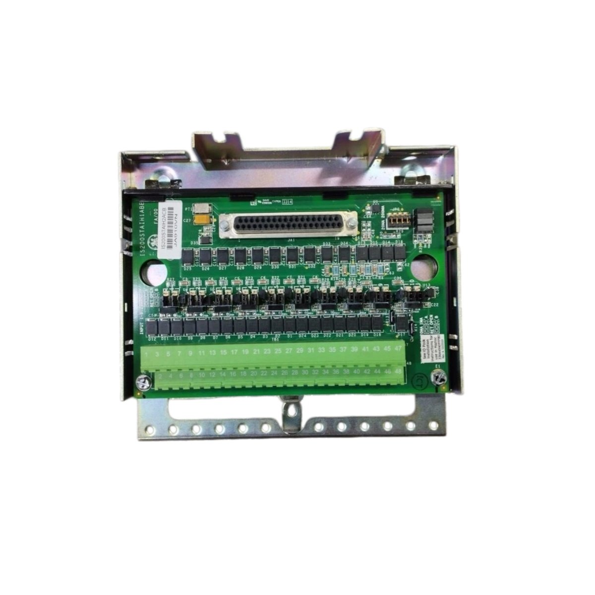
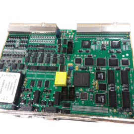
The GE IS200TRPLH1A IS200TRPLH1AEC Primary Trip Terminal Board provides emergency shutdown termination for Mark VIe systems. This board connects overspeed and over-temperature protection devices to the controller. You will find it in gas turbine and steam turbine safety applications. It accepts critical trip signals from speed sensors and temperature switches. Therefore, this unit ensures fail-safe turbine shutdown during emergency conditions.
The GE IS200TRPLH1A IS200TRPLH1AEC Primary Trip Terminal Board measures 225 mm in height and 148 mm in width. Its depth reaches 32 mm for DIN rail mounting. The unit weighs approximately 0.52 kilograms. It contains no active electronic components at all. Twenty-two screw terminals accept trip device wiring and shield connections. Additionally, you get two 50-pin ribbon headers for protection pack connection.
Key Technical Specifications
| Parameter | Value |
|---|---|
| Manufacturer | GE Energy / General Electric |
| Model | IS200TRPLH1A / IS200TRPLH1AEC |
| Product Type | Primary Trip Terminal Board |
| Trip Channels | 10 (redundant configuration) |
| Signal Type | 24 VDC (emergency shutdown) |
| Terminal Count | 22 (screw type) |
| Wire Gauge Range | 24 to 14 AWG |
| I/O Pack Connector | 2 x 50-pin ribbon header |
| Height | 225 mm |
| Width | 148 mm |
| Depth | 32 mm |
| Weight | 0.52 kg |
| Internal Components | 0 (fully passive) |
| Energy Storage | 0 Joules (none) |
| Mounting Type | 35 mm DIN rail |
| PCB Layer Count | 6-layer |
| Dielectric Strength | 2500 VAC |
| Operating Temperature | -30°C to +65°C |
| Terminal Pitch | 6.5 mm spacing |
Internal Architecture and Energy Storage
The GE IS200TRPLH1A IS200TRPLH1AEC Primary Trip Terminal Board stores absolutely no electrical energy internally. It contains no capacitors, batteries, or semiconductor devices. Twenty-two screw terminals connect directly to two 50-pin ribbon headers through heavy copper traces. Each trace provides a low-resistance path critical for trip circuit integrity. The PCB uses a 6-layer construction for maximum noise immunity. A metal DIN rail clip provides secure mounting and chassis grounding. The board includes separate ground terminals for sensitive shield connections. Each terminal has a test point for safety function verification.
Connection Interfaces and Wiring Details
You will find 22 screw terminals arranged for ten trip channels plus grounds. Each trip channel uses two terminals for the 24 VDC signal and return. Connect the overspeed switch positive wire to the channel IN terminal. Connect the switch return wire to the adjacent COM terminal. The GE IS200TRPLH1A IS200TRPLH1AEC Primary Trip Terminal Board includes two 50-pin female headers on the PCB. Connect one header to the protection I/O pack using a shielded ribbon cable. Connect the second header to another terminal board for redundant channel expansion. Use 14 to 18 AWG wire for all trip circuit connections. Keep trip wiring separate from non-critical signals.
Installation and Mounting Steps
You mount this terminal board onto standard 35 mm DIN rail. First, hook the top clip onto the rail edge securely. Then, press the bottom toward the rail until it snaps into place. Slide the board along the rail for easy panel layout. Connect all trip device wiring before attaching the protection pack. The GE IS200TRPLH1A IS200TRPLH1AEC Primary Trip Terminal Board requires no external power supply. It simply routes trip signals between safety devices and the protection pack. For high-vibration areas, add end stops on both rail ends. Label each terminal with its corresponding trip function clearly. Connect the ribbon cable between the terminal board and the protection I/O pack. Test each trip channel with a continuity checker before system startup.
Details
| Weight | 0.1 kg |
|---|---|
| Dimensions | 25 × 108 × 127 mm |
Reviews
There are no reviews yet.