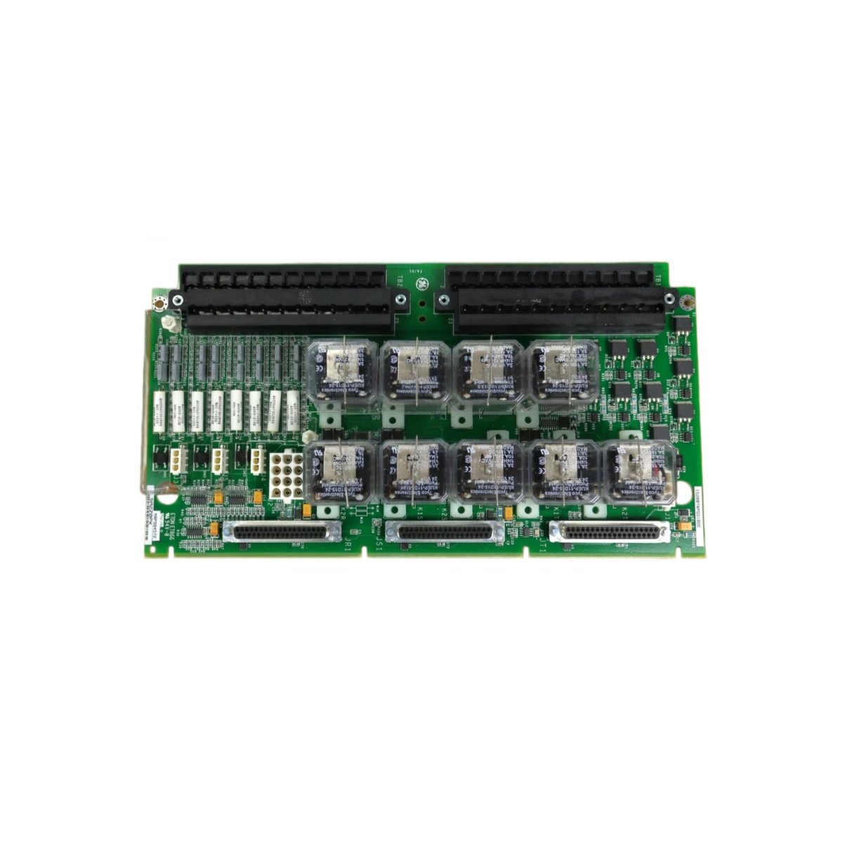
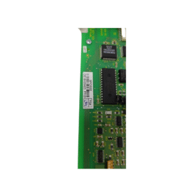
The GE IS200TRPAH1A IS200TRPAH1AFB Terminal Circuit Board provides field wiring termination for Mark VIe systems. This board connects turbine sensors and actuators to the main controller. You will find it in gas turbine and steam turbine control cabinets. It accepts discrete and analog signals from field devices. Therefore, this unit simplifies installation and maintenance of turbine controls.
The GE IS200TRPAH1A IS200TRPAH1AFB Terminal Circuit Board measures 220 mm in height and 145 mm in width. Its depth reaches 30 mm for DIN rail mounting. The unit weighs approximately 0.48 kilograms. It contains no active electronic components at all. Thirty screw terminals accept field wiring from sensors and actuators. Additionally, you get two 50-pin ribbon headers for I/O pack connection.
Key Technical Specifications
| Parameter | Value |
|---|---|
| Manufacturer | GE Energy / General Electric |
| Model | IS200TRPAH1A / IS200TRPAH1AFB |
| Product Type | Terminal Circuit Board |
| Number of Terminals | 30 (screw type) |
| Wire Gauge Range | 24 to 14 AWG |
| Terminal Pitch | 6.5 mm |
| I/O Pack Connectors | 2 x 50-pin ribbon header |
| Height | 220 mm |
| Width | 145 mm |
| Depth | 30 mm |
| Weight | 0.48 kg |
| Internal Components | 0 (fully passive) |
| Energy Storage | 0 Joules (none) |
| Mounting Type | 35 mm DIN rail |
| PCB Layer Count | 4-layer |
| Operating Temperature | -30°C to +65°C |
| Housing Material | Epoxy-coated |
Internal Architecture and Energy Storage
The GE IS200TRPAH1A IS200TRPAH1AFB Terminal Circuit Board stores absolutely no electrical energy internally. It contains no capacitors, batteries, or semiconductor devices. Thirty screw terminals connect directly to two 50-pin ribbon headers through copper traces. Each trace provides a short electrical path from the field wire to the I/O pack. The PCB uses a 4-layer construction for noise reduction. A metal DIN rail clip provides secure mounting and chassis grounding. The board includes a ground terminal for field shield connections. Each terminal has a test point for probe access.
Connection Interfaces and Wiring Details
You will find 30 screw terminals arranged in three rows of ten. Each terminal accepts 24 to 14 AWG copper wire. Use a 3.5mm flathead screwdriver to tighten each screw. Strip 8 mm of insulation from each wire before insertion. Then, insert the bare copper into the square terminal opening. Tighten the screw to 0.6 Nm of torque maximum. The GE IS200TRPAH1A IS200TRPAH1AFB Terminal Circuit Board includes two 50-pin female headers on the PCB. Connect one header to the I/O pack using a shielded ribbon cable. Connect the second header to another terminal board for daisy-chaining. Each channel connects the field device between the terminal and its corresponding header pin.
Installation and Mounting Steps
You mount this terminal board onto standard 35 mm DIN rail. First, hook the top clip onto the rail edge securely. Then, press the bottom toward the rail until it snaps into place. Slide the board along the rail for easy panel layout. Connect all field wiring before attaching the I/O pack. The GE IS200TRPAH1A IS200TRPAH1AFB Terminal Circuit Board requires no external power supply. It simply routes signals between field devices and the I/O pack. For high-vibration areas, add end stops on both rail ends. Label each terminal with its corresponding channel number clearly. Connect the ribbon cable between the terminal board and the I/O pack. Test each connection with a continuity checker before system startup.
Details
| Weight | 0.1 kg |
|---|---|
| Dimensions | 25 × 108 × 127 mm |
Reviews
There are no reviews yet.