
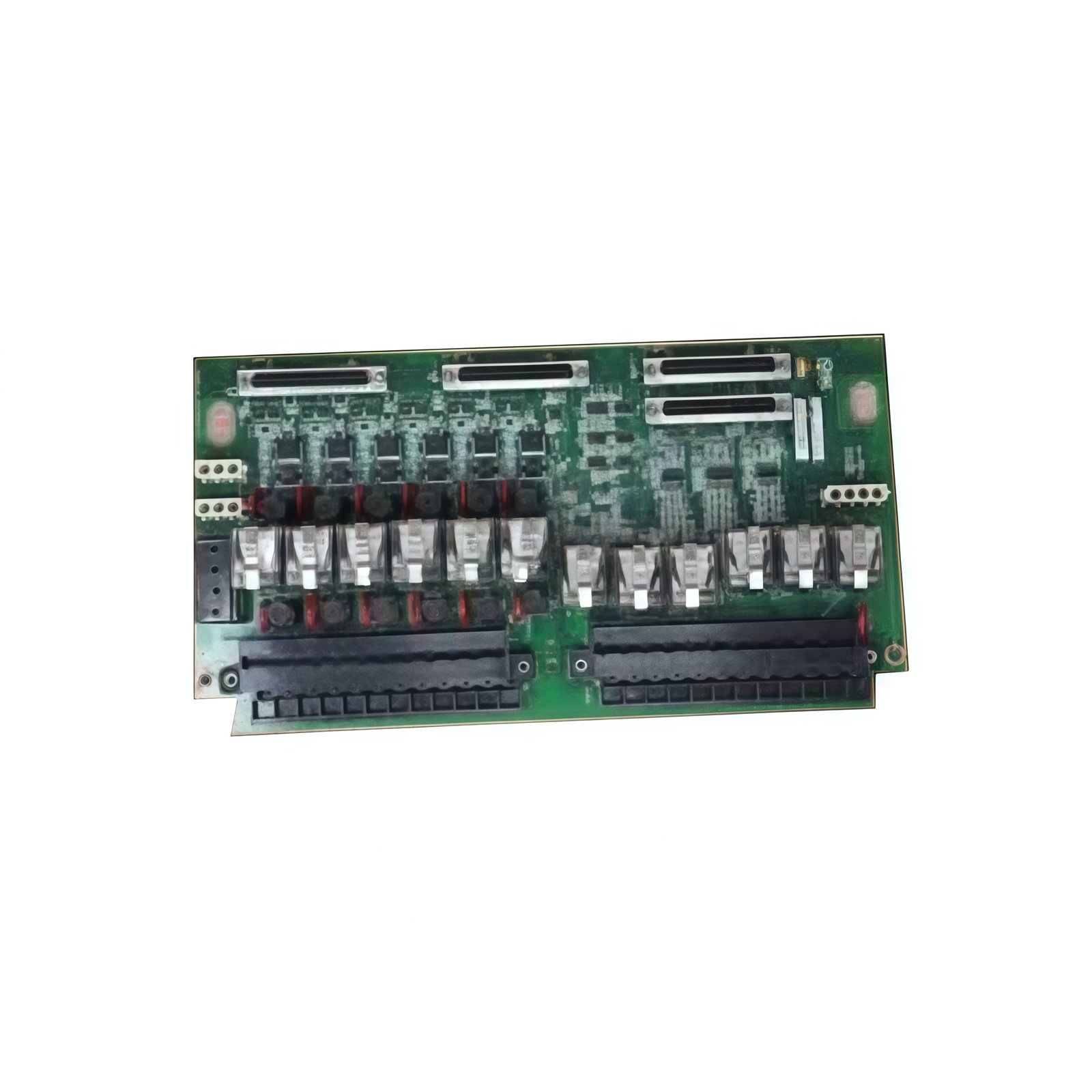
Core Function of This Relay Output Board
The GE IS200TRLYH1BGF controls field actuators and indicator devices directly. This relay output board provides 16 independent electromechanical relay channels. Each channel switches loads for solenoid valves, contactors, or alarm lamps. Consequently, the module handles discrete control tasks within turbine management systems.
Physical Dimensions and Board Construction
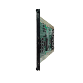
This relay output board measures 275 mm in total length. Its width reaches 190 mm for a standard PCB form factor. The board thickness stands at 28 mm including relay heights. You will find 312 discrete components on this flame-retardant substrate. These include 16 pluggable relays, driver transistors, and flyback diodes. The GE IS200TRLYH1BGF weighs approximately 620 grams for stable mounting.
Output Channels and Contact Ratings
Each relay channel provides a single-pole double-throw contact arrangement. The normally open contacts handle 250 V AC at 5 A maximum. The normally closed contacts handle 250 V AC at 3 A maximum. All contacts support DC loads up to 30 V at similar current ratings. Each relay includes a visible status LED for quick troubleshooting.
Coil Drivers and Protection Circuits
The GE IS200TRLYH1BGF uses 24 V DC relay coils for all 16 outputs. A dedicated Darlington driver array powers every coil individually. Each channel includes a flyback diode to suppress voltage spikes. This diode protects the driver circuitry from inductive kickback. The board also provides fuse holders for external load protection.
Connector Types and Field Wiring
Two 36-pin high-density headers connect this board to the controller. Additionally, four 10-pin terminal blocks accept field device wiring. Each terminal accepts wire gauges from 0.5 to 2.5 mm². The board also includes a separate 4-pin connector for auxiliary 24 V DC power. Gold-plated contacts ensure reliable connections in industrial environments.
Energy Storage and Power Requirements
The GE IS200TRLYH1BGF draws 180 mA from a 5 V DC logic supply. It also requires 450 mA from a 24 V DC coil supply at full load. The board incorporates eight 47 µF electrolytic capacitors for local decoupling. However, these capacitors do not retain relay state after power loss. Total stored energy reaches approximately 0.08 joules at nominal voltage.
| Parameter | Specification |
|---|---|
| Model | IS200TRLYH1BGF |
| Brand | GE (General Electric) |
| Category | Relay Output Board |
| Length x Width | 275 x 190 mm |
| Thickness | 28 mm |
| Weight | 620 grams |
| Component Count | 312 |
| Output channels | 16 independent relays |
| Contact form | SPDT per channel |
| NO contact rating | 5 A at 250 V AC |
| NC contact rating | 3 A at 250 V AC |
| DC load rating | 30 V at same currents |
| Relay coil voltage | 24 V DC |
| Filter capacitors | 8 x 47 µF |
| Total stored energy | 0.08 Joules |
| Logic supply | 180 mA at 5 V DC |
| Coil supply | 450 mA at 24 V DC |
| Main connectors | 2 x 36-pin high-density |
Installation and Performance Notes
You must install this board in a Mark VIe VME rack slot. Always connect external fuses for each output channel. Then, verify that the load current does not exceed the contact rating. The module provides optical isolation between logic and relay circuits. The board operates reliably from -20°C to +60°C ambient temperature.
Details
| Weight | 0.1 kg |
|---|---|
| Dimensions | 25 × 108 × 127 mm |
Reviews
There are no reviews yet.