Why This Relay Output Board Controls Field Actuators Reliably
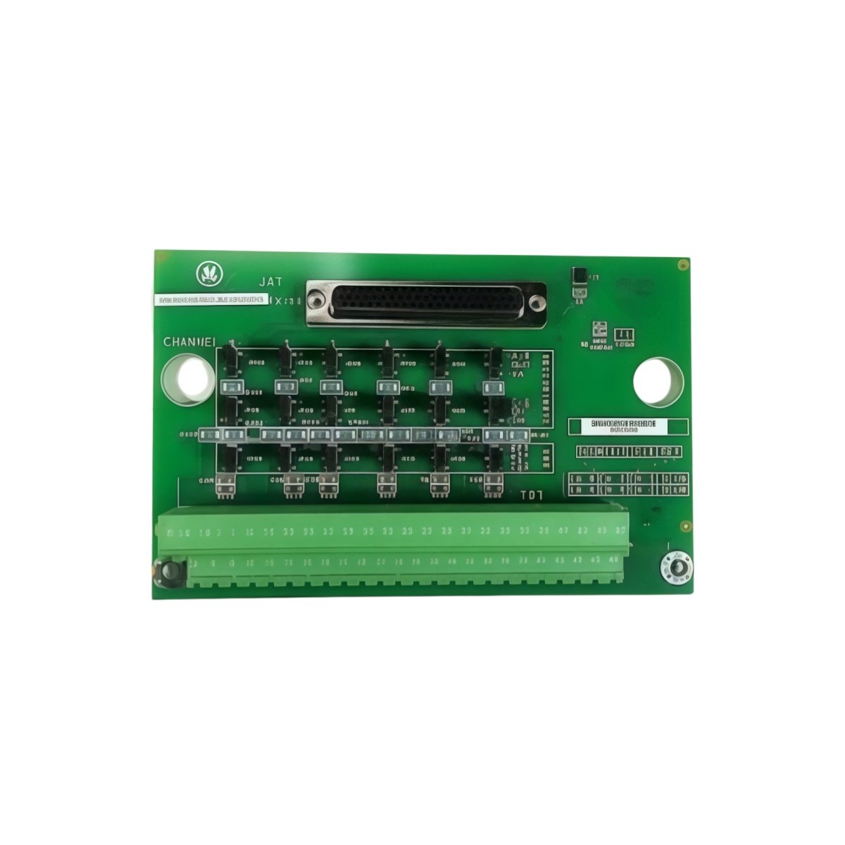
The GE IS200TRLYH1B IS200TRLYH1BGF provides relay outputs for Mark V turbine control. This board connects the main controller to field actuators and solenoids. It switches high-current loads based on control system commands. For this reason, the GE IS200TRLYH1B IS200TRLYH1BGF operates valves, starters, and auxiliary equipment directly. It also isolates the control logic from high-power circuits.
Technical Specifications of the Board
We engineer this GE IS200TRLYH1B IS200TRLYH1BGF for reliable load switching. It operates on a 24V DC power supply with ±10% tolerance. The board features twelve independent relay outputs for field devices. Each relay includes a visible status LED indicator. On‑board capacitors suppress arcing across relay contacts.
| Specification | Value | Additional Notes |
|---|---|---|
| Full Model | GE IS200TRLYH1B IS200TRLYH1BGF | Relay Output Terminal Board |
| Control Voltage | 24V DC ±10% | For relay coil activation |
| Relay Outputs | Twelve form C relays | SPDT configuration |
| Contact Rating | 5A at 250V AC, 5A at 30V DC | For inductive loads |
| Status Indication | Twelve LED indicators | One per relay channel |
| Arc Suppression | On‑board capacitor network | Reduces contact wear |
| Response Time | Less than 15 milliseconds | From command to contact change |
| Dimensions | 220mm x 120mm x 60mm | Fits Mark V termination racks |
| Weight | 0.78 kg (approximately) | Includes all relay hardware |
| Interface Type | Backplane connector + screw terminals | Heavy‑duty for field wiring |
| Component Count | 78 discrete components | Relays, capacitors, resistors, LEDs |
Hardware Architecture and Output Control
The GE IS200TRLYH1B IS200TRLYH1BGF receives activation signals from the backplane. Each relay coil connects to a dedicated driver transistor. Moving to output side, twelve sets of form C contacts handle field wiring. The board latches relay states during momentary power interruptions. Moreover, the H1BGF revision adds enhanced contact protection diodes. This improvement extends relay life when switching inductive loads.
Installation and Wire Transfer Guidelines
You must de‑energize the entire cabinet before removing this board. Disconnect all field wiring from the GE IS200TRLYH1B IS200TRLYH1BGF terminals first. Label each wire according to its terminal position. Then remove the board from its rack slot carefully. Insert the replacement board into the exact same slot position. Reconnect each wire to its corresponding terminal. Skipping this step may cause incorrect device operation. Additionally, test each relay output after completing the installation.
Details
| Weight | 0.1 kg |
|---|---|
| Dimensions | 25 × 108 × 127 mm |

Reviews
There are no reviews yet.