

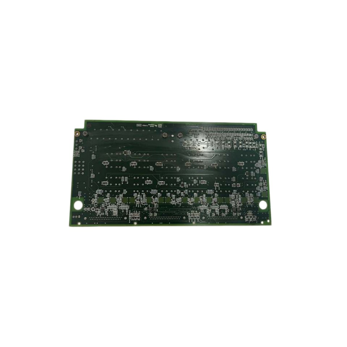
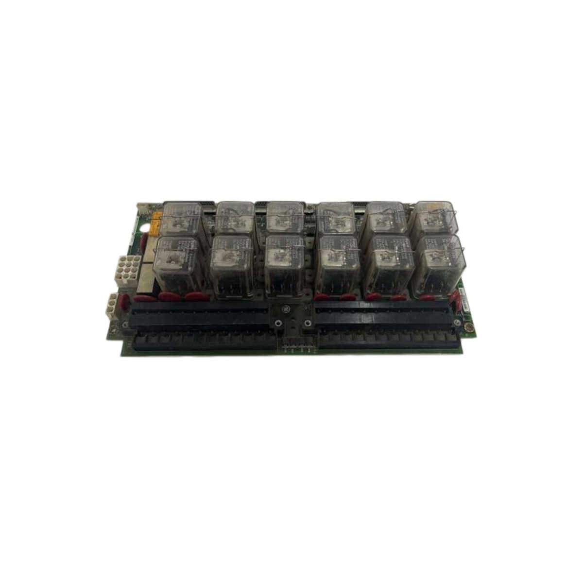
The GE IS200TREGH1B turbine emergency terminal board provides critical I/O termination for turbine protection systems. This module interfaces emergency shutdown sensors and actuators with the main control system. The board incorporates redundant power inputs and high-isolation channels for maximum safety integrity.
Technical Specifications
| Parameter | Specification |
|---|---|
| Product Type | Emergency terminal board |
| Model Code | IS200TREGH1B |
| Termination Channels | 32 I/O points (configurable) |
| Input Types | 24V DC digital, 4-20mA analog |
| Output Types | 24V DC / 2A relay (form C) |
| Isolation Voltage | 1500V AC (I/O to backplane) |
| Dimensions (W x H x D) | 300 x 200 x 45 mm |
| Weight | 1.5 kg |
| Terminal Type | Screw-clamp (rising cage) |
| Wire Gauge | 0.5 mm² to 4 mm² (solid/stranded) |
| Redundant Power Inputs | 2 x 24V DC (diode-ORed) |
| Power Consumption | 24V / 300 mA (typical) |
| Internal Components | 32 x optocouplers, 8 x relay drivers, 4 x fuse holders, 2 x diode arrays |
| Fuse Protection | 4 x 2A (fast-blow, per group) |
| LED Indicators | 32 x green (channel status), 2 x green (power status) |
| Backplane Connector | 2 x 50-pin ribbon cable headers |
| Operating Temperature | -20°C to +70°C |
| Storage Temperature | -40°C to +85°C |
| Protection Class | IP20 |
| Mounting | DIN rail (35mm) or panel |
| Approvals | IEC 61508 (SIL 2), CE, UL, CSA |
Comprehensive Emergency Shutdown Termination
The GE IS200TREGH1B provides 32 configurable I/O points for emergency shutdown functions. These channels handle both digital and analog signals from safety sensors. Users can wire emergency stop pushbuttons, pressure switches, and temperature transmitters directly. The board also terminates actuator signals for trip valves and alarms.
High Isolation for Safety Integrity
Galvanic isolation of 1500V AC separates all I/O channels from the backplane circuits. This high isolation level prevents electrical faults from propagating to the control system. Thirty-two optocouplers provide the isolation barrier for every I/O point. This design ensures the board meets IEC 61508 SIL 2 safety requirements.
Redundant Power Architecture
Two independent 24V DC inputs connect through diode-OR circuits for redundancy. This architecture ensures continuous operation if one power supply fails. The diode array prevents reverse current from one input to the other. Power status LEDs confirm the availability of each redundant supply.
Grouped Fuse Protection
Four 2A fast-blow fuses protect groups of eight I/O channels each. This grouping isolates faults to specific channel groups without disabling the entire board. Users can easily replace blown fuses without special tools. Fuse holders remain accessible on the front panel for quick maintenance.
Visual Status Indication for All Channels
Thirty-two green LEDs display the real-time status of each I/O channel individually. Two green power LEDs show the status of each redundant power input. This comprehensive visual feedback speeds up troubleshooting during maintenance. Operators can identify channel states without using additional test equipment.
Rugged Mechanical Design for Turbine Applications
The board measures 300 x 200 x 45 mm and weighs 1.5 kg for robust installation. Screw-clamp terminals accept solid or stranded wires from 0.5 mm² to 4 mm². Two 50-pin ribbon cable headers connect the board to the control processor. The IP20-rated housing protects against accidental contact and dust ingress.
Details
| Weight | 0.1 kg |
|---|---|
| Dimensions | 25 × 108 × 127 mm |
Reviews
There are no reviews yet.