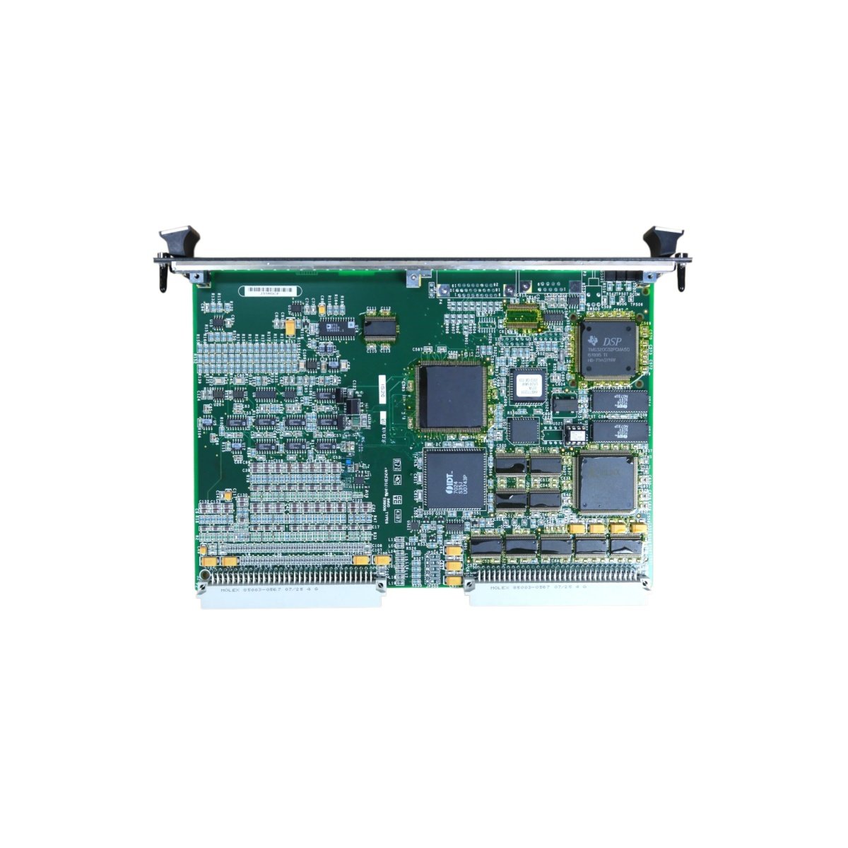
This GE IS200TDBTH8A IS200TDBTH8APR2 TMR Contact I/O Terminal Board provides triple-modular redundant contact inputs for Mark VI systems. The board interfaces between field devices and three independent control channels. You will find this component in many GE safety-critical turbine applications. The IS200TDBTH8APR2 variant includes a rugged conformal coating for harsh environments.
Technical Specifications
| Parameter | Specification |
|---|---|
| Full Model | GE IS200TDBTH8A IS200TDBTH8APR2 TMR Contact I/O Terminal Board |
| Category | TMR Contact I/O Terminal Board |
| Contact Inputs | 24 Triple-Modular Redundant Channels |
| Input Voltage Range | 24V to 250V AC or DC |
| Maximum Current | 10 mA per Input |
| Response Time | Less than 2 milliseconds |
| Isolation | 2500 V RMS between Channels |
| Dimensions (H x W) | 280 mm x 220 mm |
| Weight | Approximately 1.65 kg |
| Connectors | 3 x 50-Pin Ribbon Headers, 1 x Terminal Block |
| Component Count | 248 Discrete Components |
| Energy Storage | None (Passive Board) |
Triple-Modular Redundant I/O Features
The GE IS200TDBTH8A IS200TDBTH8APR2 TMR Contact I/O Terminal Board routes each field signal to three independent controllers. The board uses a voted output scheme for critical safety functions. Each input channel includes surge suppression for reliable operation. Furthermore, the board provides status feedback for each channel’s health condition. Consequently, the system tolerates any single controller failure without losing critical signals.
Installation and Connection Steps
Mount this GE IS200TDBTH8A IS200TDBTH8APR2 TMR Contact I/O Terminal Board in the lower section of any Mark VI cabinet. First, secure the board using four M6 mounting bolts at the corners. After that, connect field wiring to the terminal block following the printed labels. Then, attach the three ribbon cables to each of the three controller boards. Finally, verify each channel’s continuity before applying power to the system.
Energy Discharge and Safety Notice
This GE IS200TDBTH8A IS200TDBTH8APR2 TMR Contact I/O Terminal Board stores no significant energy. Therefore, you can handle it immediately after power removal. However, field wiring may carry hazardous voltages from external sensors. Always disconnect external power before touching any terminal.
Status Indication and Diagnostics
Twenty-four green LEDs indicate the active state of each contact input. A yellow LED illuminates when any channel detects a wiring fault. A red LED flashes when two or three channels show mismatched states. These indicators help technicians troubleshoot TMR voting discrepancies without special tools.
Details
| Weight | 0.1 kg |
|---|---|
| Dimensions | 25 × 108 × 127 mm |
Reviews
There are no reviews yet.