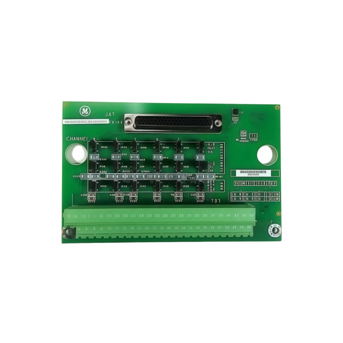
Why This Contact Input Board Monitors Field Switch States
The GE IS200TBCIS2C IS200TBCIS2CCD terminates discrete contact inputs for Mark V turbines. This board connects limit switches, pushbuttons, and relay contacts. It provides a central termination point for all status signals. For this reason, the GE IS200TBCIS2C IS200TBCIS2CCD simplifies cabinet layout and field maintenance. It also filters electrical noise from contact bounce.
Technical Specifications of the Board
We engineer this GE IS200TBCIS2C IS200TBCIS2CCD for clean contact signal termination. It operates on a 24V DC power supply for input conditioning. The board features sixteen independent contact input channels. Each channel includes optical isolation for noise immunity. On‑board capacitors filter transient spikes from field wiring.
| Specification | Value | Additional Notes |
|---|---|---|
| Full Model | GE IS200TBCIS2C IS200TBCIS2CCD | Contact Input Terminal Board |
| Power Supply | 24V DC ±10% | For input conditioning |
| Input Channels | Sixteen discrete channels | For status contacts |
| Input Voltage | 24V DC nominal | Wetting voltage provided |
| Input Current | 10mA per channel | For contact wetting |
| Isolation | Optical coupler per channel | 2500V RMS isolation |
| Filtering | Debounce circuit per channel | 5ms typical |
| Status Indication | Sixteen LED indicators | One per channel |
| Dimensions | 220mm x 120mm x 60mm | Fits Mark V termination racks |
| Weight | 0.62 kg (approximately) | Includes all opto components |
| Interface Type | Backplane connector + screw terminals | Gold‑plated for reliability |
| Component Count | 128 discrete components | Optos, capacitors, resistors, LEDs |
Hardware Architecture and Signal Flow
The GE IS200TBCIS2C IS200TBCIS2CCD uses optical isolators for each input channel. These isolators separate field wiring from control logic. Moving to input side, terminal blocks receive signals from dry contacts. The board then provides 24V wetting voltage for reliable contact sensing. Moreover, the C revision adds enhanced ESD protection on all inputs. This improvement prevents static damage during field wiring changes.
Installation and Wire Transfer Guidelines
You must de‑energize the entire cabinet before removing this board. Disconnect all field wiring from the GE IS200TBCIS2C IS200TBCIS2CCD first. Label each wire according to its channel number. Then remove the board from its rack slot carefully. Insert the replacement board into the exact same slot position. Reconnect each wire to its corresponding channel terminal. Skipping this step may cause incorrect status readings. Additionally, verify each input state after completing the installation.
Details
| Weight | 0.1 kg |
|---|---|
| Dimensions | 25 × 108 × 127 mm |

Reviews
There are no reviews yet.