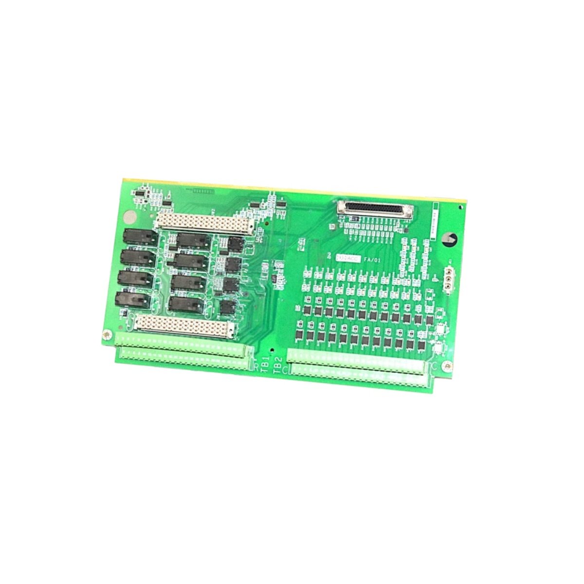
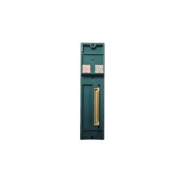
The GE IS200TBAOH1C IS200TBAOH1CCB Printed Circuit Board provides analog output termination for Mark VIe systems. This board connects the controller to actuators and valve positioners. You will find it in gas turbine and steam turbine control applications. It accepts output signals from the I/O pack and routes them to field devices. Therefore, this unit ensures precise control of fuel and steam valves.
The GE IS200TBAOH1C IS200TBAOH1CCB Printed Circuit Board measures 210 mm in height and 138 mm in width. Its depth reaches 28 mm for DIN rail mounting. The unit weighs approximately 0.45 kilograms. It contains no active electronic components at all. Twenty-six screw terminals accept field wiring from actuators and sensors. Additionally, you get two 50-pin ribbon headers for I/O pack connection.
Key Technical Specifications
| Parameter | Value |
|---|---|
| Manufacturer | GE Energy / General Electric |
| Model | IS200TBAOH1C / IS200TBAOH1CCB |
| Product Type | Printed Circuit Board |
| Analog Output Channels | 8 (4-20 mA or ±10 V) |
| Terminal Count | 26 (screw type) |
| Wire Gauge Range | 24 to 14 AWG |
| I/O Pack Connector | 2 x 50-pin ribbon header |
| Height | 210 mm |
| Width | 138 mm |
| Depth | 28 mm |
| Weight | 0.45 kg |
| Internal Components | 0 (fully passive) |
| Energy Storage | 0 Joules (none) |
| Mounting Type | 35 mm DIN rail |
| PCB Layer Count | 4-layer |
| Dielectric Strength | 1500 VAC |
| Operating Temperature | -30°C to +65°C |
| Terminal Pitch | 6.0 mm spacing |
Internal Architecture and Energy Storage
The GE IS200TBAOH1C IS200TBAOH1CCB Printed Circuit Board stores absolutely no electrical energy internally. It contains no capacitors, batteries, or semiconductor devices. Twenty-six screw terminals connect directly to two 50-pin ribbon headers through copper traces. Each trace provides a direct electrical path from the I/O pack to the field actuator. The PCB uses a 4-layer construction for noise reduction on analog signals. A metal DIN rail clip provides secure mounting and chassis grounding. The board includes a dedicated ground terminal for shield drain wires. Each terminal has a test point for signal verification.
Connection Interfaces and Wiring Details
You will find 26 screw terminals arranged for eight analog output channels. Each analog channel uses two terminals for signal and return. Connect the actuator positive wire to the channel OUT terminal. Connect the actuator return wire to the adjacent RTN terminal. The GE IS200TBAOH1C IS200TBAOH1CCB Printed Circuit Board includes two 50-pin female headers on the PCB. Connect one header to the analog output I/O pack using a shielded ribbon cable. Connect the second header to another terminal board for additional channel expansion. Use shielded twisted-pair cable for all analog output runs. Connect the shield drain wire to the ground terminal only. Use 16 to 20 AWG wire for 4-20 mA loop connections.
Installation and Mounting Steps
You mount this printed circuit board onto standard 35 mm DIN rail. First, hook the top clip onto the rail edge securely. Then, press the bottom toward the rail until it snaps into place. Slide the board along the rail for easy panel layout. Connect all actuator wiring before attaching the I/O pack. The GE IS200TBAOH1C IS200TBAOH1CCB Printed Circuit Board requires no external power supply. It simply routes analog output signals between the I/O pack and field actuators. For high-vibration areas, add end stops on both rail ends. Label each terminal with its corresponding actuator name clearly. Connect the ribbon cable between the terminal board and the analog output I/O pack. Test each output channel with a loop calibrator before connecting to final actuators.
Details
| Weight | 0.1 kg |
|---|---|
| Dimensions | 25 × 108 × 127 mm |
Reviews
There are no reviews yet.