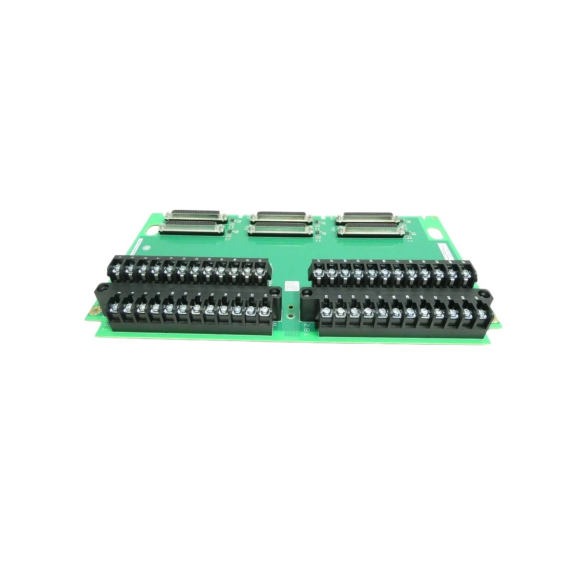
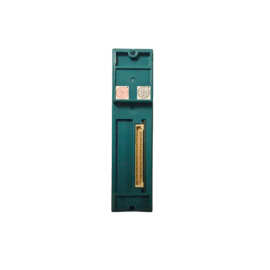
The GE IS200TAMBH1A IS200TAMBH1ABA Acoustic Monitoring Terminal Board connects acoustic sensors to Mark VIe systems. This board terminates signals from dynamic pressure sensors and microphones. You will find it in gas turbine combustion monitoring applications. It accepts up to eight acoustic input channels for flame detection. Therefore, this unit helps detect combustion instability and flame blowout conditions.
The GE IS200TAMBH1A IS200TAMBH1ABA Acoustic Monitoring Terminal Board measures 218 mm in height and 142 mm in width. Its depth reaches 30 mm for DIN rail mounting. The unit weighs approximately 0.46 kilograms. It contains no active electronic components at all. Twenty screw terminals accept acoustic sensor wiring and shield connections. Additionally, you get two 50-pin ribbon headers for I/O pack connection.
Key Technical Specifications
| Parameter | Value |
|---|---|
| Manufacturer | GE Energy / General Electric |
| Model | IS200TAMBH1A / IS200TAMBH1ABA |
| Product Type | Acoustic Monitoring Terminal Board |
| Acoustic Channels | 8 (dynamic pressure) |
| Signal Type | ±10 V AC (20 Hz to 20 kHz) |
| Terminal Count | 20 (screw type) |
| Wire Gauge Range | 24 to 18 AWG |
| I/O Pack Connector | 2 x 50-pin ribbon header |
| Height | 218 mm |
| Width | 142 mm |
| Depth | 30 mm |
| Weight | 0.46 kg |
| Internal Components | 0 (fully passive) |
| Energy Storage | 0 Joules (none) |
| Mounting Type | 35 mm DIN rail |
| PCB Layer Count | 4-layer |
| Shield Grounding | Dedicated terminal |
| Operating Temperature | -30°C to +65°C |
| Terminal Pitch | 6.5 mm spacing |
Internal Architecture and Energy Storage
The GE IS200TAMBH1A IS200TAMBH1ABA Acoustic Monitoring Terminal Board stores absolutely no electrical energy internally. It contains no capacitors, batteries, or semiconductor devices. Twenty screw terminals connect directly to two 50-pin ribbon headers through copper traces. Each acoustic channel uses two terminals for the differential signal pair. The PCB uses a 4-layer construction with optimized grounding for low-noise performance. A metal DIN rail clip provides secure mounting and chassis grounding. The board includes a dedicated ground terminal for each shield connection. Each terminal has a test point for signal verification.
Connection Interfaces and Wiring Details
You will find 20 screw terminals arranged for eight acoustic channels. Each acoustic channel uses two terminals for signal positive and negative. Connect the dynamic pressure sensor positive wire to the CH+ terminal. Connect the sensor negative wire to the adjacent CH- terminal. The GE IS200TAMBH1A IS200TAMBH1ABA Acoustic Monitoring Terminal Board includes two 50-pin female headers on the PCB. Connect one header to the acoustic I/O pack using a shielded ribbon cable. Connect the second header to another terminal board for additional channel expansion. Use high-quality shielded twisted-pair cable for all acoustic signal runs. Connect the shield drain wire to the dedicated ground terminal. Keep acoustic wiring away from high-voltage power cables.
Installation and Mounting Steps
You mount this terminal board onto standard 35 mm DIN rail. First, hook the top clip onto the rail edge securely. Then, press the bottom toward the rail until it snaps into place. Slide the board along the rail for easy panel layout. Connect all acoustic sensor wiring before attaching the I/O pack. The GE IS200TAMBH1A IS200TAMBH1ABA Acoustic Monitoring Terminal Board requires no external power supply. It simply routes acoustic signals between sensors and the I/O pack. For high-vibration areas, add end stops on both rail ends. Label each terminal with its corresponding sensor name clearly. Connect the ribbon cable between the terminal board and the acoustic monitoring I/O pack. Test each channel with a signal generator before commissioning.
Details
| Weight | 0.1 kg |
|---|---|
| Dimensions | 25 × 108 × 127 mm |
Reviews
There are no reviews yet.