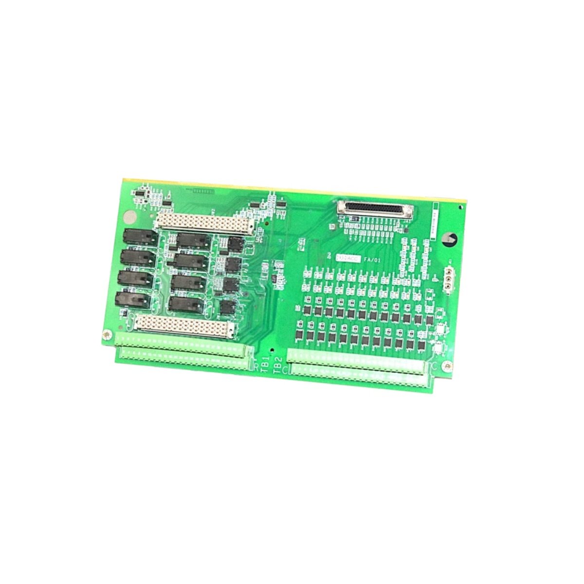
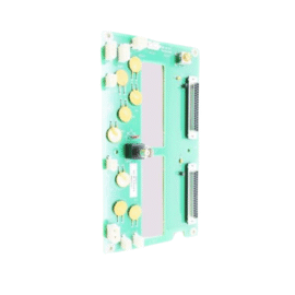
The GE IS200STURH4A IS200STURH4AEC Speedtronic Turbine Control PCB Board manages turbine sequencing and protection logic. This board handles critical control functions for gas and steam turbines. You will find it in Mark VIe systems for power generation applications. It communicates with I/O packs through the high-speed InSync bus. Therefore, this unit coordinates all turbine control and protection activities.
The GE IS200STURH4A IS200STURH4AEC Speedtronic Turbine Control PCB Board measures 245 mm in height and 168 mm in width. Its depth reaches 42 mm for chassis mounting. The unit weighs approximately 0.82 kilograms. It contains one 32-bit processor and 32 MB of RAM. Two InSync bus ports provide redundant communication to remote I/O packs. Additionally, you get twelve status LEDs for diagnostics.
Key Technical Specifications
| Parameter | Value |
|---|---|
| Manufacturer | GE Energy / General Electric |
| Model | IS200STURH4A / IS200STURH4AEC |
| Product Type | Speedtronic Turbine Control PCB Board |
| Processor | 32-bit @ 200 MHz |
| Program Memory | 16 MB Flash |
| Data Memory | 32 MB RAM (battery-backed) |
| InSync Ports | 2 (RS-485 serial, redundant) |
| Communication Speed | 1 Mbps |
| Maximum I/O Packs | 64 per bus |
| Battery | Lithium (memory backup) |
| Height | 245 mm |
| Width | 168 mm |
| Depth | 42 mm |
| Weight | 0.82 kg |
| Status LEDs | 12 (PWR, RUN, ERR, COM) |
| Energy Storage | ≈ 600 µF (capacitive) |
| Power Consumption | 650 mA @ 5 VDC |
| Operating Temperature | -30°C to +65°C |
| Mounting Method | Chassis (6 screws) |
| Layer Count | 8-layer PCB |
Internal Architecture and Energy Storage
The GE IS200STURH4A IS200STURH4AEC Speedtronic Turbine Control PCB Board stores moderate energy in its power filter. Electrolytic capacitors hold approximately 600 microfarads total capacitance. A 32-bit processor runs at 200 MHz for fast logic execution. This processor includes a floating-point unit for complex turbine calculations. Sixteen MB of flash memory stores turbine control application code. Thirty-two MB of battery-backed RAM holds real-time process data and alarms. Two independent InSync bus ports provide redundant communication paths. A lithium battery maintains RAM data during power outages for up to 3 years. Twelve LEDs show power, run, error, and communication status clearly.
Connection Interfaces and Wiring Details
You will find two 9-pin D-sub connectors on the front panel. These ports connect to the InSync bus for I/O pack communication. Use shielded twisted-pair cable for all InSync bus connections. The GE IS200STURH4A IS200STURH4AEC Speedtronic Turbine Control PCB Board also includes a 10-pin JTAG port for debugging. Twelve LEDs show power, run, error, and communication status. A green RUN LED lights up when the board executes application code. A red ERR LED indicates a processor or configuration fault. An amber COM LED flashes during InSync bus activity.
Configuration and Installation Steps
You mount this board onto a metal chassis with six screws. First, drill six 5 mm holes matching the mounting pattern. Then, secure the board using M4 screws with lock washers. Connect the 5 VDC power wires to the terminal block. The GE IS200STURH4A IS200STURH4AEC Speedtronic Turbine Control PCB Board consumes 650 mA from the supply. Use the Toolbox software to download turbine control logic. Configure the InSync bus parameters including baud rate and node addressing. Set the board’s unique address using the rotary switches. Install the lithium battery before powering on the system. Verify that all twelve LEDs show correct status after boot-up. Test communication with all attached I/O packs before turbine operation.
Details
| Weight | 0.1 kg |
|---|---|
| Dimensions | 25 × 108 × 127 mm |
Reviews
There are no reviews yet.