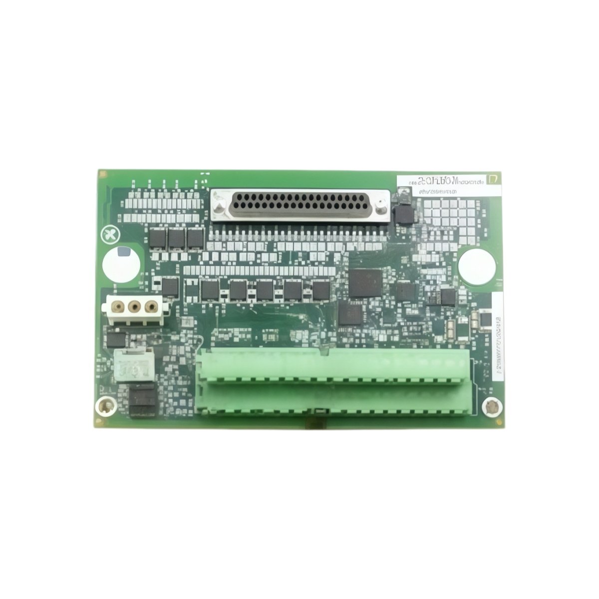
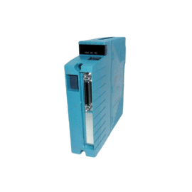
This GE IS200STCIH6A IS200STCIH6ADD DIN Rail Contact Terminal Board mounts directly on standard DIN rails for easy installation. The board provides screw terminal connections for field contact inputs and outputs. You will find this component in many GE Mark VI turbine control cabinets. The IS200STCIH6ADD variant includes a rugged conformal coating for harsh environments.
Technical Specifications
| Parameter | Specification |
|---|---|
| Full Model | GE IS200STCIH6A IS200STCIH6ADD DIN Rail Contact Terminal Board |
| Category | DIN Rail Contact Terminal Board |
| Terminal Points | 48 Screw-Type Terminals |
| Maximum Voltage | 300 V AC or DC |
| Maximum Current | 10 A per Terminal |
| Wire Gauge | 26 AWG to 14 AWG |
| Mounting Type | TS35 DIN Rail (Top Hat) |
| Dimensions (H x W) | 110 mm x 210 mm |
| Weight | Approximately 0.65 kg |
| Connectors | 2 x 37-Pin D-Sub |
| Component Count | 12 Passive Components |
| Energy Storage | None (Passive Board) |
Field Wiring and DIN Rail Features
The GE IS200STCIH6A IS200STCIH6ADD DIN Rail Contact Terminal Board clips onto any TS35 DIN rail without tools. Each terminal includes a labeled position for easy identification during maintenance. The board routes signals directly to the 37-pin D-Sub connectors for controller connection. Furthermore, it includes simple RC filter networks on critical contact inputs. Consequently, noise from field wiring does not affect control signal accuracy.
Installation and Connection Steps
Mount this GE IS200STCIH6A IS200STCIH6ADD DIN Rail Contact Terminal Board inside any standard control cabinet. First, snap the board onto the TS35 DIN rail firmly. After that, attach field wiring to the screw terminals following the printed labels. Then, connect the two D-Sub cables to the corresponding controller boards. Finally, verify each connection before applying power to the system.
Energy Discharge and Safety Notice
This GE IS200STCIH6A IS200STCIH6ADD DIN Rail Contact Terminal Board stores no significant energy. Therefore, you can handle it immediately after power removal. However, field wiring may carry hazardous voltages from external devices. Always disconnect external power before touching any terminal.
Status Indication and Diagnostics
This terminal board has no active indicators or LEDs. However, each terminal position includes a test point for meter connection. You can verify signal presence using these test points without removing wires. The clear labeling helps technicians identify contact channels quickly during troubleshooting.
Details
| Weight | 0.1 kg |
|---|---|
| Dimensions | 25 × 108 × 127 mm |
Reviews
There are no reviews yet.