Why This Speedtronic Terminal Board Organizes Critical Turbine Signals
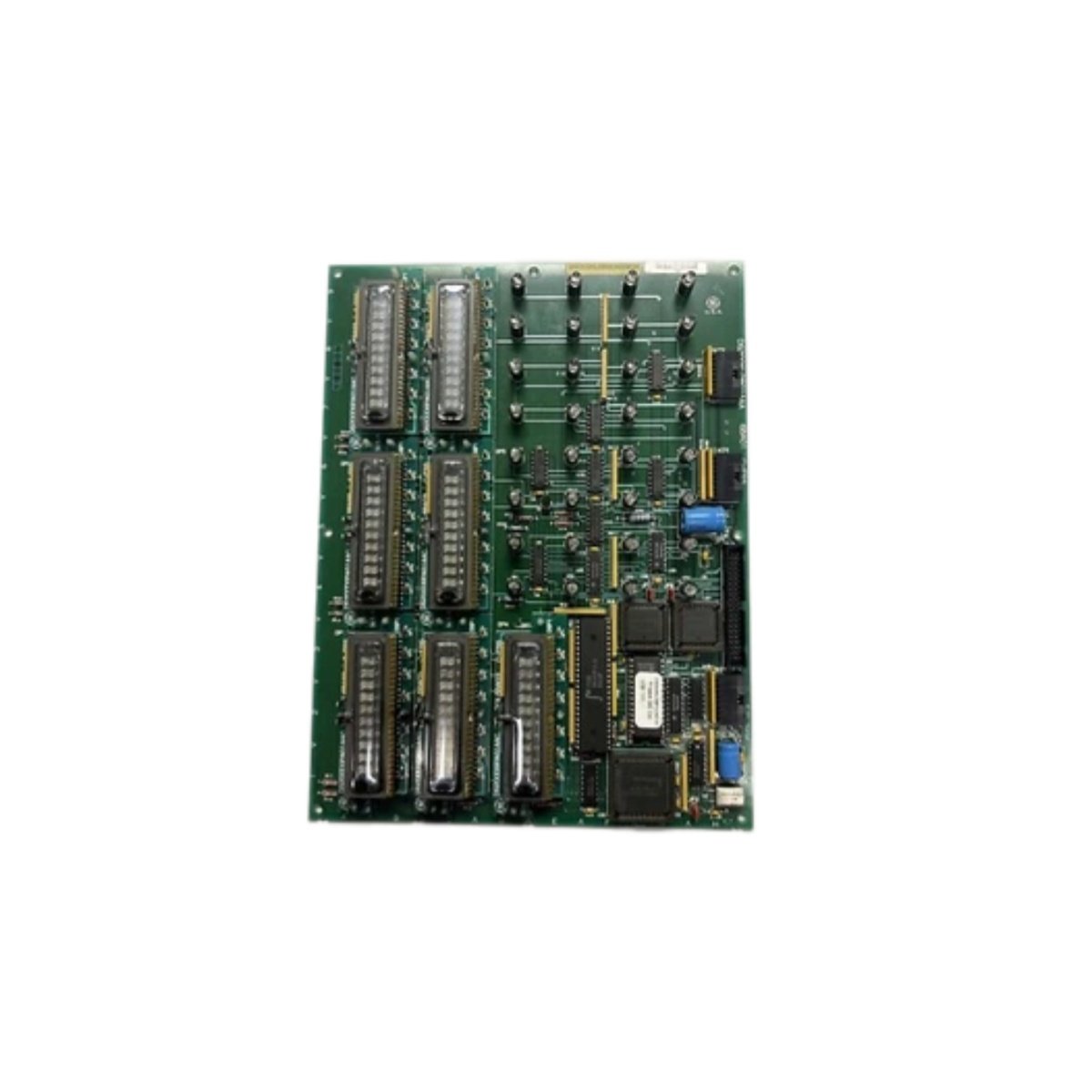
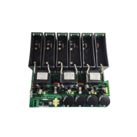
The GE IS200SPIDG1A IS200SPIDG1ABA terminates Speedtronic control signals for Mark V turbines. This board connects speed sensors, temperature probes, and pressure transmitters. It provides a central junction for all critical I/O wiring. For this reason, the GE IS200SPIDG1A IS200SPIDG1ABA simplifies cabinet layout and field maintenance. It also reduces wiring errors by grouping related signals together.
Technical Specifications of the Board
We engineer this GE IS200SPIDG1A IS200SPIDG1ABA for clean signal termination. It operates without an external power supply. The board features twenty-two terminal positions for field wiring. Each terminal accepts 14‑22 AWG copper wires securely. On‑board capacitors filter high-frequency noise from critical signal lines.
| Specification | Value | Additional Notes |
|---|---|---|
| Full Model | GE IS200SPIDG1A IS200SPIDG1ABA | Speedtronic Terminal Board |
| Power Supply | Passive operation | No external power needed |
| Terminal Positions | Twenty-two positions | For control signal wiring |
| Wire Gauge | 14‑22 AWG | Solid or stranded copper |
| Signal Filtering | On‑board capacitor array | Reduces electrical noise |
| Current Rating | 5A per terminal | Maximum continuous current |
| Voltage Rating | 250V AC / 30V DC | Isolation between terminals |
| Channel Grouping | Speed, temp, pressure | Organized by signal function |
| Dimensions | 220mm x 120mm x 55mm | Fits Mark V termination racks |
| Weight | 0.50 kg (approximately) | Lightweight for easy mounting |
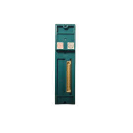
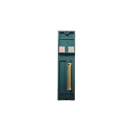
| Interface Type | Backplane connector + screw terminals | Gold‑plated for reliability |
| Component Count | 26 discrete components | Capacitors only for filtering |
Hardware Architecture and Signal Routing
The GE IS200SPIDG1A IS200SPIDG1ABA contains no active electronic components. This board relies on passive filtering for noise reduction. Moving to input side, terminal blocks receive signals from field sensors. The board then routes these signals directly to the backplane connector. Moreover, the G1ABA revision adds additional ground reference points. This improvement reduces crosstalk between adjacent control channels.
Installation and Wire Transfer Guidelines
You must disconnect all field wiring before removing the old board. Label each wire with its corresponding terminal number on the GE IS200SPIDG1A IS200SPIDG1ABA first. Then transfer each wire to the exact same position on the replacement board. Verify all screw terminals tighten securely to prevent loose connections. Skipping this step may cause intermittent control signal loss. Additionally, verify each signal path after completing the installation.
Details
| Weight | 0.1 kg |
|---|---|
| Dimensions | 25 × 108 × 127 mm |
Reviews
There are no reviews yet.