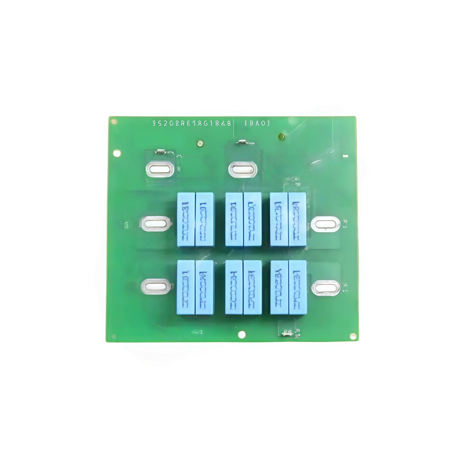
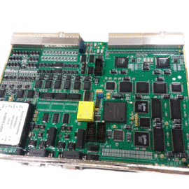
This GE IS200RCSBG1B IS200RCSBG1BAA Turbine Control Snubber Board protects power semiconductors from voltage transients. The board connects directly across each SCR in the turbine control bridge circuit. You will find this component in many GE Mark VI excitation and drive systems. The IS200RCSBG1BAA variant includes the standard factory configuration without conformal coating.
Technical Specifications
| Parameter | Specification |
|---|---|
| Full Model | GE IS200RCSBG1B IS200RCSBG1BAA Turbine Control Snubber Board |
| Category | Turbine Control Snubber Board |
| Number of Channels | 6 Independent Snubber Circuits |
| Resistor Value | 18 Ω, 25W Wirewound per Channel |
| Capacitor Value | 0.22 µF, 1000V Polypropylene per Channel |
| Peak Voltage Rating | 1000 V |
| dv/dt Suppression | 550 V/µs Maximum |
| Dimensions (H x W) | 200 mm x 140 mm |
| Weight | Approximately 0.72 kg |
| Connectors | 6 x Quick-Disconnect Terminals |
| Component Count | 12 Resistors, 6 Capacitors |
| Energy Storage | 0.22 µF per Channel (Total 1.32 µF) |
Transient Suppression and Protection Features
The GE IS200RCSBG1B IS200RCSBG1BAA Turbine Control Snubber Board limits voltage rise across each semiconductor during commutation. Each channel combines an 18 Ω resistor with a 0.22 µF capacitor. This RC network absorbs energy from parasitic inductances in the power circuit. Furthermore, the board prevents false triggering from high dv/dt events. Consequently, your SCR bridge operates reliably even under harsh switching conditions.
Installation and Connection Steps
Mount this GE IS200RCSBG1B IS200RCSBG1BAA Turbine Control Snubber Board near the power bridge in the turbine control cabinet. First, connect each channel’s terminals across one SCR’s anode and cathode. After that, verify all six connections match the correct phase assignments. Then, secure the board using four M3 mounting screws. Finally, check that no terminals touch adjacent circuits before powering up.
Energy Discharge and Safety Notice
This GE IS200RCSBG1B IS200RCSBG1BAA Turbine Control Snubber Board stores energy in its six capacitors. Therefore, you must wait at least one minute after power removal. The capacitors discharge through their series resistors naturally. Never short the terminals to discharge them faster.
Status Indication and Diagnostics
This snubber board has no active indicators or LEDs. However, you can test each RC network with an LCR meter. A failed capacitor typically shows as a short or open circuit. A burned resistor indicates excessive switching energy in that phase.
Details
| Weight | 0.1 kg |
|---|---|
| Dimensions | 25 × 108 × 127 mm |
Reviews
There are no reviews yet.