Why This Gate Driver Board Controls Power Semiconductor Switching
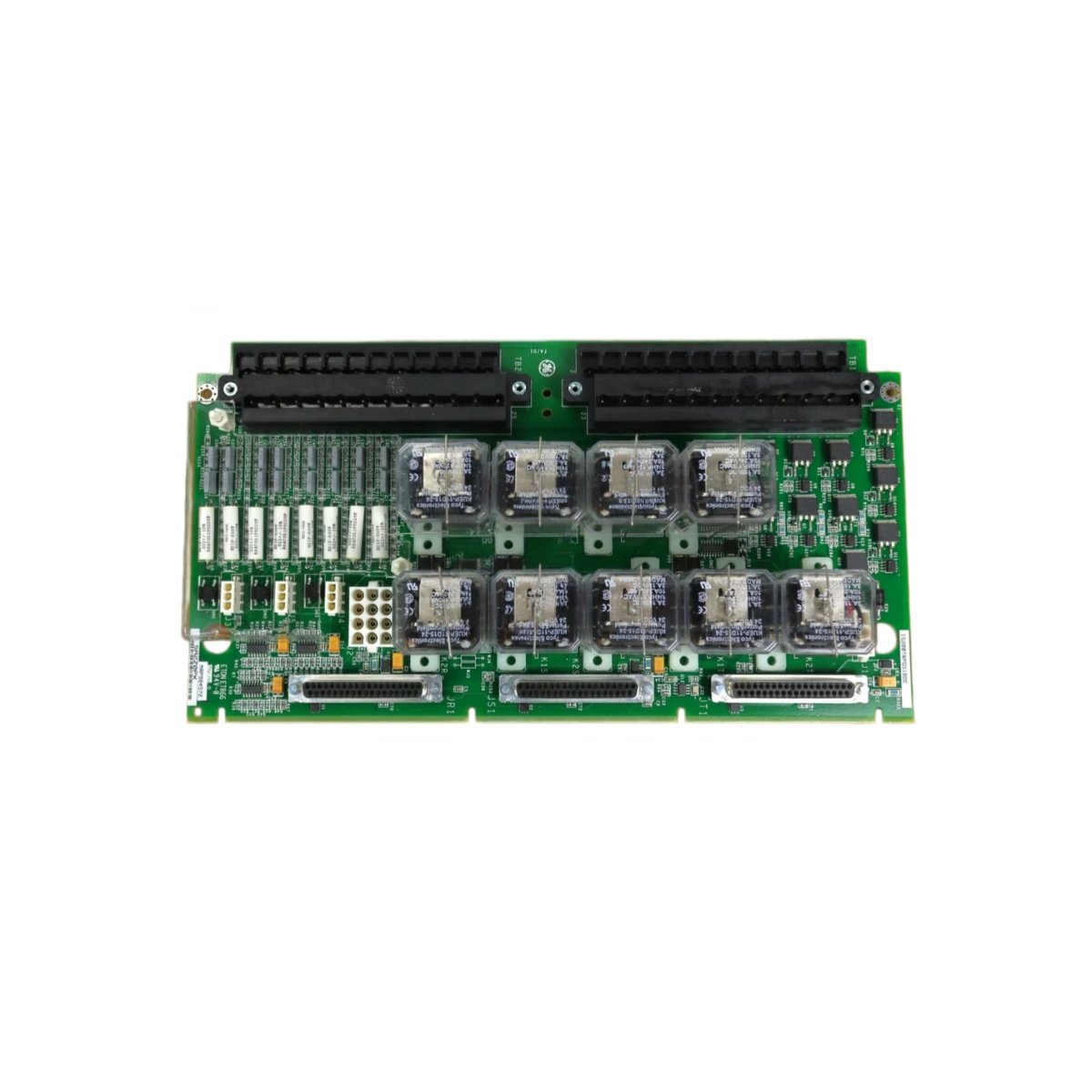
The GE IS200PICHG1A IS200PICHG1ADA drives gate signals for power thyristors and IGBTs. This board translates low‑voltage control commands into high‑current gate pulses. It ensures precise timing for each switching device in the power stack. For this reason, the GE IS200PICHG1A IS200PICHG1ADA enables efficient AC/DC power conversion. It also protects power semiconductors from incorrect gate drive conditions.
Technical Specifications of the Board
We engineer this GE IS200PICHG1A IS200PICHG1ADA for reliable gate drive performance. It operates on a 24V DC power supply with ±10% tolerance. The board features six independent gate drive channels. Each channel provides isolated output for thyristor or IGBT control. On‑board capacitors store energy for fast gate pulse generation.
| Specification | Value | Additional Notes |
|---|---|---|
| Full Model | GE IS200PICHG1A IS200PICHG1ADA | Gate Driver Board |
| Power Supply | 24V DC ±10% | For control logic |
| Gate Channels | Six independent channels | For thyristors or IGBTs |
| Output Voltage | +15V / -8V typical | Gate turn‑on and turn‑off |
| Peak Output Current | 5A per channel | For fast gate charging |
| Isolation Voltage | 2500V RMS | Between input and output |
| Switching Frequency | Up to 5kHz | For power converter control |
| Protection Features | Desaturation detection | Short circuit protection |
| Energy Storage | Capacitor bank | 470µF for pulse energy |
| Dimensions | 200mm x 110mm x 60mm | Fits Mark V power racks |
| Weight | 0.68 kg (approximately) | Robust construction |
| Interface Type | Backplane connector + terminal block | For gate wiring |
| Component Count | 96 discrete components | Drivers, transformers, capacitors |
Hardware Architecture and Gate Signal Flow
The GE IS200PICHG1A IS200PICHG1ADA includes six isolated gate driver ICs. Each driver receives logic signals from the backplane. Moving to output side, pulse transformers provide isolation for each gate channel. The board monitors each power device for desaturation faults. Moreover, the G1ADA revision adds enhanced short‑circuit protection. This improvement shuts down the gate driver during output faults.
Installation and Replacement Guidelines
You must de‑energize the entire power cabinet before removing this board. Disconnect all gate wiring from the GE IS200PICHG1A IS200PICHG1ADA first. Label each wire according to its channel number. Then remove the board from its rack slot carefully. Insert the replacement board into the exact same slot position. Reconnect each gate wire to its corresponding channel. Skipping this step may cause incorrect power device switching. Additionally, verify each gate pulse shape after installation.
Details
| Weight | 0.1 kg |
|---|---|
| Dimensions | 25 × 108 × 127 mm |
Reviews
There are no reviews yet.