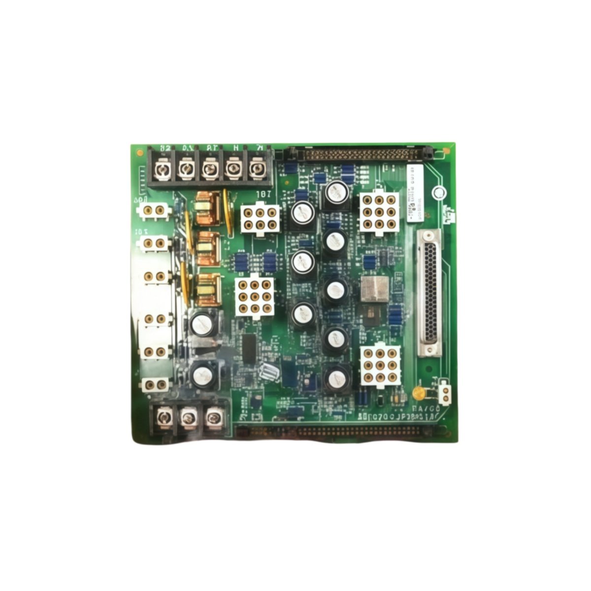
This GE IS200JPDMG1A IS200JPDMG1ACC Power Distribution Board distributes DC power across Mark VI rack systems. The board receives raw input and provides filtered outputs to multiple card slots. You will find this component in many GE turbine control cabinets globally. The IS200JPDMG1ACC variant includes a rugged conformal coating for harsh environments.
Technical Specifications
| Parameter | Specification |
|---|---|
| Full Model | GE IS200JPDMG1A IS200JPDMG1ACC Power Distribution Board |
| Category | Power Distribution Board |
| Input Voltage | 125 VDC or 250 VDC (Field Selectable) |
| Distribution Slots | 10 VME Card Positions |
| Output Rails | +5V, +12V, -12V, +24V |
| Maximum Current | 22 A Total across All Rails |
| Filtering | 2-Stage LC Low-Pass Filter per Rail |
| Dimensions (H x W) | 270 mm x 190 mm |
| Weight | Approximately 1.55 kg |
| Connectors | 2 x Power Input Stabs, 10 x P1/P2 Backplane |
| Component Count | 84 Discrete Components |
| Energy Storage | 5 x 1000 µF Bulk Capacitors |
Power Distribution and Protection Features
The GE IS200JPDMG1A IS200JPDMG1ACC Power Distribution Board delivers clean power to all ten rack slots. Each output rail has independent overcurrent protection with fuses. The board includes a two-stage filter for each voltage rail separately. Furthermore, it provides status feedback for each rail’s health condition. Consequently, the main controller knows exactly which rail has failed.
Installation and Connection Steps
Mount this GE IS200JPDMG1A IS200JPDMG1ACC Power Distribution Board as the backplane inside any Mark VI rack chassis. First, connect the external DC supply to the two power input stabs. After that, secure the board using factory-installed standoffs and screws. Then, insert each VME card into its designated slot carefully. Finally, verify all rail voltages before powering up any other cards.
Energy Discharge and Safety Notice
This GE IS200JPDMG1A IS200JPDMG1ACC Power Distribution Board stores significant energy in its capacitors. Therefore, you must wait at least three minutes after power removal. The five bulk capacitors discharge through internal bleeder resistors. Never insert or remove cards while the backplane remains powered.
Status Indication and Diagnostics
A green LED indicates the presence of valid input power on the board. Four yellow LEDs show the status of each output voltage rail. A red LED illuminates when any rail fuse has opened due to overload. These indicators help technicians verify power distribution without removing any cards.
Details
| Weight | 0.1 kg |
|---|---|
| Dimensions | 25 × 108 × 127 mm |

Reviews
There are no reviews yet.