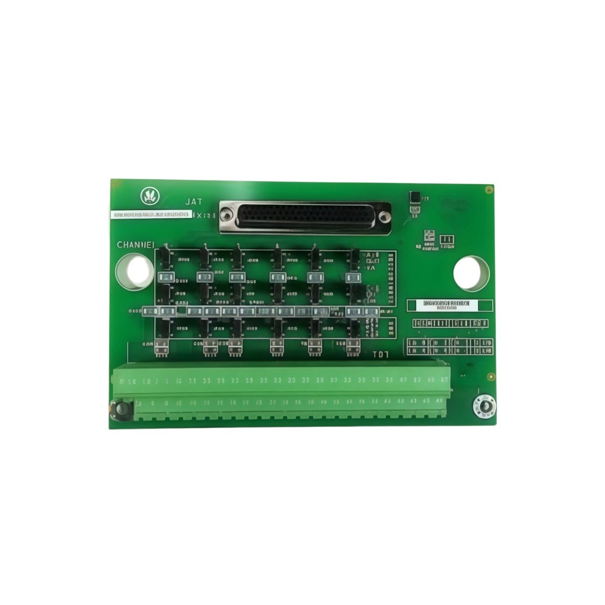
The GE IS200ISBEH2A IS200ISBEH2ABB InSync Bus Extender Board extends the InSync serial bus for Mark VIe systems. This board connects multiple I/O packs across longer distances. You will find it in gas turbine and steam turbine control cabinets. It regenerates the bus signal to maintain data integrity. Therefore, this unit allows flexible placement of remote I/O devices.
The GE IS200ISBEH2A IS200ISBEH2ABB InSync Bus Extender Board measures 180 mm in height and 120 mm in width. Its depth reaches 30 mm for panel mounting. The unit weighs approximately 0.28 kilograms. It contains one bus repeater chip and two isolation transformers. Two 9-pin D-sub connectors provide the InSync bus interfaces. Additionally, you get four status LEDs for diagnostics.
Key Technical Specifications
| Parameter | Value |
|---|---|
| Manufacturer | GE Energy / General Electric |
| Model | IS200ISBEH2A / IS200ISBEH2ABB |
| Product Type | InSync Bus Extender Board |
| Bus Type | InSync serial (RS-485) |
| Number of Ports | 2 (D-sub 9-pin) |
| Maximum Cable Length | 300 meters per segment |
| Repeater Type | Bi-directional regenerative |
| Isolation | 1500 VAC (transformer) |
| Height | 180 mm |
| Width | 120 mm |
| Depth | 30 mm |
| Weight | 0.28 kg |
| Internal Components | 1 repeater, 2 transformers |
| Status LEDs | 4 (PWR, TX, RX, FAULT) |
| Energy Storage | ≈ 120 µF (capacitive) |
| Power Consumption | 100 mA @ 5 VDC |
| Operating Temperature | -30°C to +65°C |
| Mounting Method | Panel (4 screws) |
Internal Architecture and Energy Storage
The GE IS200ISBEH2A IS200ISBEH2ABB InSync Bus Extender Board stores minimal energy in its power filter. Small capacitors hold approximately 120 microfarads total capacitance. A dedicated repeater chip receives and retransmits bus signals in both directions. This chip regenerates the signal waveform to eliminate distortion. Two isolation transformers provide 1500 VAC protection between ports. The board includes automatic data direction control for bi-directional operation. Four LEDs show power, transmit, receive, and fault conditions. A green PWR LED lights up when the board receives 5 VDC. A red FAULT LED indicates a bus short or termination error.
Connection Interfaces and Wiring Details
You will find two 9-pin D-sub female connectors on the board edge. Connect the incoming InSync cable to port P1. Connect the outgoing InSync cable to port P2. Use shielded twisted-pair cable for all InSync bus connections. Connect pin 2 to Data A (+) and pin 3 to Data B (-). Connect the shield drain wire to pin 5 (ground). The GE IS200ISBEH2A IS200ISBEH2ABB InSync Bus Extender Board requires 5 VDC power from the Mark VIe backplane. A yellow TX LED flashes during data transmission. A yellow RX LED flashes during data reception. Install termination resistors at both ends of the extended bus only.
Installation and Configuration Steps
You mount this board onto a flat metal panel with four screws. First, drill four 4 mm holes matching the mounting pattern. Then, secure the board using M3 screws with standoffs. Connect the 5 VDC power wires to the terminal block. The GE IS200ISBEH2A IS200ISBEH2ABB InSync Bus Extender Board draws 100 mA from the supply. Connect the incoming InSync cable to port P1. Connect the next extender or I/O pack to port P2. Do not exceed 300 meters between any two extenders. The board automatically configures itself with no jumpers. Verify that the green PWR LED turns on after power-up. Test bus communication with a diagnostic tool before final deployment.
Details
| Weight | 0.1 kg |
|---|---|
| Dimensions | 25 × 108 × 127 mm |
Reviews
There are no reviews yet.