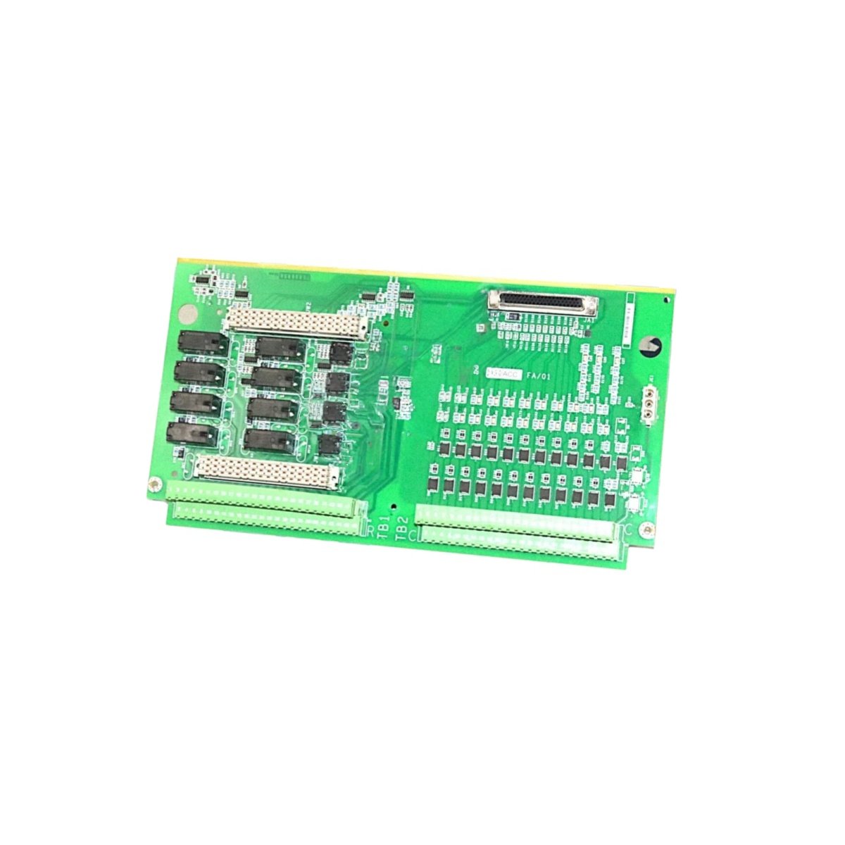
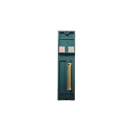
The GE IS200IGDMH1A IS200IGDMH1AAA Printed Circuit Board manages I/O data distribution for Mark VIe systems. This board connects field I/O packs to the main turbine controller. You will find it in gas turbine and steam turbine control applications. It provides high-speed data transfer between multiple I/O devices. Therefore, this unit ensures reliable communication for critical turbine operations.
The GE IS200IGDMH1A IS200IGDMH1AAA Printed Circuit Board measures 240 mm in height and 160 mm in width. Its depth reaches 38 mm for chassis mounting. The unit weighs approximately 0.52 kilograms. It contains one 16-bit microcontroller and three bus transceivers. Two 50-pin ribbon connectors provide I/O pack interfaces. Additionally, you get eight status LEDs for diagnostics.
Key Technical Specifications
| Parameter | Value |
|---|---|
| Manufacturer | GE Energy / General Electric |
| Model | IS200IGDMH1A / IS200IGDMH1AAA |
| Product Type | Printed Circuit Board |
| Microcontroller | 16-bit @ 40 MHz |
| Memory | 512 KB Flash, 128 KB RAM |
| I/O Interfaces | 2 x 50-pin ribbon headers |
| Communication Protocol | InSync serial bus |
| Data Transfer Rate | 1 Mbps |
| Maximum I/O Packs | 32 per board |
| Height | 240 mm |
| Width | 160 mm |
| Depth | 38 mm |
| Weight | 0.52 kg |
| Bus Transceivers | 3 |
| Status LEDs | 8 (PWR, COM, ERR) |
| Energy Storage | ≈ 250 µF (capacitive) |
| Power Consumption | 350 mA @ 5 VDC |
| Operating Temperature | -30°C to +65°C |
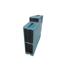
| Mounting Method | Chassis (4 screws) |
| Layer Count | 6-layer PCB |
Internal Architecture and Energy Storage
The GE IS200IGDMH1A IS200IGDMH1AAA Printed Circuit Board stores minimal energy in its power filter. Small capacitors hold approximately 250 microfarads total capacitance. A 16-bit microcontroller runs I/O scanning routines at 40 MHz. This controller manages data exchange with up to 32 remote I/O packs. Three bus transceivers buffer and drive the InSync communication lines. The board uses a 6-layer PCB construction for noise reduction. Two inner layers provide dedicated power and ground planes. A hardware watchdog timer resets the microcontroller if it freezes. Eight LEDs show power, communication, and error status clearly.
Connection Interfaces and Wiring Details
You will find two 50-pin ribbon cable headers on the board edge. Connect these headers to I/O packs using shielded ribbon cables. The GE IS200IGDMH1A IS200IGDMH1AAA Printed Circuit Board also includes a 10-pin JTAG header. Use this header for firmware updates and debugging purposes. Eight LEDs indicate power, active communication, and fault conditions. A green PWR LED lights up when the board receives 5 VDC. A yellow COM LED flashes during data transmission on each port. A red ERR LED indicates a bus conflict or I/O pack failure.
Installation and Configuration Steps
You mount this board onto a metal chassis with four screws. First, drill four 4 mm holes matching the mounting pattern. Then, secure the board using M3 screws with standoffs. Connect the 5 VDC power wires to the terminal block. The GE IS200IGDMH1A IS200IGDMH1AAA Printed Circuit Board consumes 350 mA from the supply. Connect the ribbon cables to all I/O packs in the system. Use the Toolbox software to assign I/O pack addresses. Configure the board as a master or slave on the InSync bus. Download the configuration to the board’s flash memory. Verify that no red ERR LEDs remain lit after power-up. Test communication with each I/O pack before turbine startup.
Details
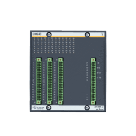
| Weight | 0.1 kg |
|---|---|
| Dimensions | 25 × 108 × 127 mm |
Reviews
There are no reviews yet.