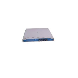
The GE IS200EXHSG4A IS200EXHSG4AEC exciter terminal board connects field contactors to Mark VI excitation systems. This board provides a reliable interface between the exciter controller and field devices. You will find this terminal board in GE Mark VI exciter control cabinets. Its high-density design packs eight relay outputs into a single slot.
Exciter Output Architecture
This terminal board provides eight high-current relay output channels. Consequently, it controls multiple field contactors from one board. The GE IS200EXHSG4A IS200EXHSG4AEC includes screw terminals for easy field wiring. Moreover, each output channel features an LED status indicator. You can monitor contactor states directly from the board.
Technical Specifications
| Parameter | Value |
|---|---|
| Output Channels | 8, relay (form A, normally open) |
| Output Voltage | 24V DC or 250V AC maximum |
| Output Current | 2A continuous per channel |
| Contact Material | Silver alloy with gold plating |
| Response Time | 10 ms maximum |
| Mechanical Life | 10 million operations |
| Electrical Life | 100,000 operations at rated load |
| Dimensions | 230mm x 170mm x 30mm |
| Weight | 0.65 kg (1.43 lbs) |
| PCB Layers | 4 |
| Onboard Components | 8 relays, 8 LEDs, 8 suppression diodes |
| Connector Count | 2 (ribbon cable to driver, field output) |
| Status Indicators | 8 LEDs (one per channel, output active) |
| Energy Storage | None (passive board) |
| Isolation Voltage | 1500V (coil to contacts) |
| Coil Voltage | 24V DC (from driver board) |
| Operating Temperature | -10°C to +55°C |
| Storage Temperature | -25°C to +70°C |
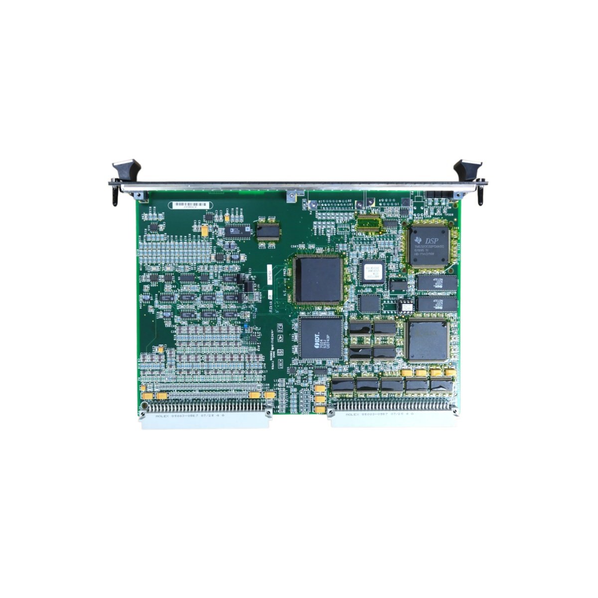
Relay Output and Status Monitoring
The unit includes high-quality relays with gold-plated contacts. Therefore, they switch low-level signals reliably without oxidation. This board replaces the IS200EXHSG4AEC version without any wiring changes. Simply remove the old board and install this one. GE designed this terminal board for single-slot installation. Hence, it fits directly into existing Mark VI rack positions.
Four PCB layers separate coil traces from contact wiring. Two connectors handle all ribbon cable and field output signals. The GE IS200EXHSG4A IS200EXHSG4AEC includes suppression diodes across each relay coil. Accordingly, it protects the driver board from inductive kickback. Eight LEDs show the active state of every output channel clearly.
Installation and Wiring Guide
You can terminate field wires using standard screw terminals. The terminals accept wire gauges from 22 AWG to 14 AWG. The GE IS200EXHSG4A IS200EXHSG4AEC works with all GE Mark VI exciter driver boards. Always strip 6-8 mm of insulation before inserting wires. Proper torque on terminal screws prevents loose connections over time.
The relay contacts are normally open and close when energized. Do not exceed the maximum current rating of 2A per channel. The GE IS200EXHSG4A IS200EXHSG4AEC provides reliable contactor control for exciter systems. Installation requires only a flathead screwdriver for field wiring. This board operates in non-condensing environments with adequate clearance.
Details
| Weight | 0.1 kg |
|---|---|
| Dimensions | 25 × 108 × 127 mm |
Reviews
There are no reviews yet.