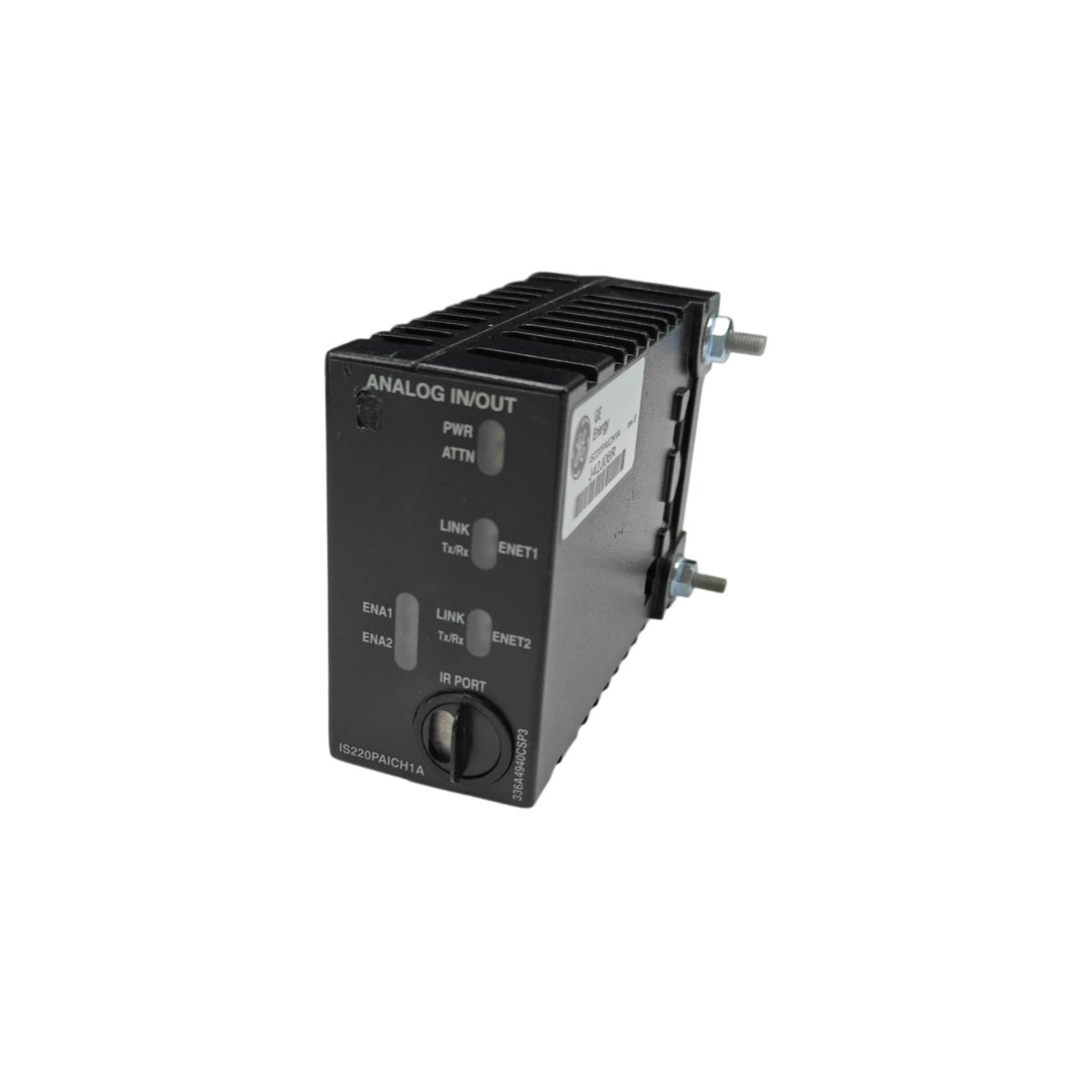
The GE IS200EXHSG3A IS200EXHSG3AEC provides high-speed signal termination for EX2100 excitation systems. This board connects field sensors to the main excitation controller. Therefore, it ensures accurate measurement of generator parameters.
Product Overview
We designed this terminal board for clean signal conditioning in noisy power plant environments. Its differential inputs reject common-mode noise from nearby high-voltage circuits. Moreover, this unit includes surge suppression for external lightning protection.
Technical Specifications
| Parameter | Specification |
|---|---|
| Dimensions | 35.6 cm (length) x 20.3 cm (width) |
| Weight | 0.85 kg (approximately 1.87 lb) |
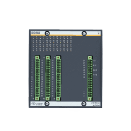
| Interface Type | Two 64-pin ribbon cables plus 40 screw terminals |
| Component Count | 94 components including RC filters and transient suppressors |
| Energy Storage | 4 ceramic capacitors (0.1 µF) plus 2 film capacitors |
| Terminal Count | 40 screw terminals in two rows of 20 |
| Wire Gauge | 30 AWG to 12 AWG solid or stranded |
| Signal Types | High-speed encoder, pulse, and analog inputs |
| Input Impedance | 1 MΩ for analog, 120 Ω for pulse channels |
| Maximum Frequency | 250 kHz for encoder inputs |
| Surge Protection | 1500W transient voltage suppressors per channel |
| Operating Voltage | 300V AC maximum between terminal groups |
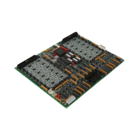
Signal Conditioning Design
The GE IS200EXHSG3A IS200EXHSG3AEC implements RC low-pass filters on all analog inputs. Its four ceramic capacitors filter high-frequency noise from each signal path. Additionally, two film capacitors provide differential mode filtering for encoder channels. You get clean signals for precise generator speed and position feedback.
Energy Storage Purpose
Four ceramic capacitors decouple power to the onboard signal conditioning ICs. Two film capacitors store energy for the encoder input comparators. These capacitors maintain signal integrity during fast pulse transitions. The transient suppressors do not store energy but clamp voltage spikes. Therefore, the board has minimal residual energy after power removal.
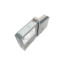
Terminal Layout
Terminals 1 through 8 carry differential encoder signals A+, A-, B+, B-, Z+, Z-.Terminals 33 through 40 distribute 24V loop power to field transmitters.
Installation Steps
Mount this board on the cabinet subpanel using four M5 screws. Connect both 64-pin ribbon cables to the excitation controller. Secure the ribbon cables with their locking latches on each end. Then route each field wire to its assigned terminal position. Tighten each terminal screw to 0.56 Nm (5 lb-in) of torque.
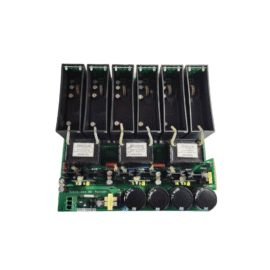
Surge Protection Features
Each input channel includes a transient voltage suppressor diode. These diodes clamp surges to 30V maximum for 1 ms duration. The board meets IEC 61000-4-5 surge immunity standards. External lightning strikes will not damage the excitation controller through this board. Replace the entire GE IS200EXHSG3A IS200EXHSG3AEC after a major surge event.
High-Speed Channel Requirements
Use twisted shielded pair for all encoder and pulse connections. Maintain a 60% to 70% duty cycle for proper comparator operation. Keep cable length under 100 meters for 250 kHz operation. The board provides 120 ohm termination resistors for differential lines. Enable this termination by installing a jumper on the selected channel.
Application Scope
This terminal board works with EX2100 and EX2100e excitation systems. Many synchronous generators use the GE IS200EXHSG3A IS200EXHSG3AEC for speed sensing. Its robust design handles continuous exposure to generator field magnetic fields.
Details
| Weight | 0.1 kg |
|---|---|
| Dimensions | 25 × 108 × 127 mm |
Reviews
There are no reviews yet.