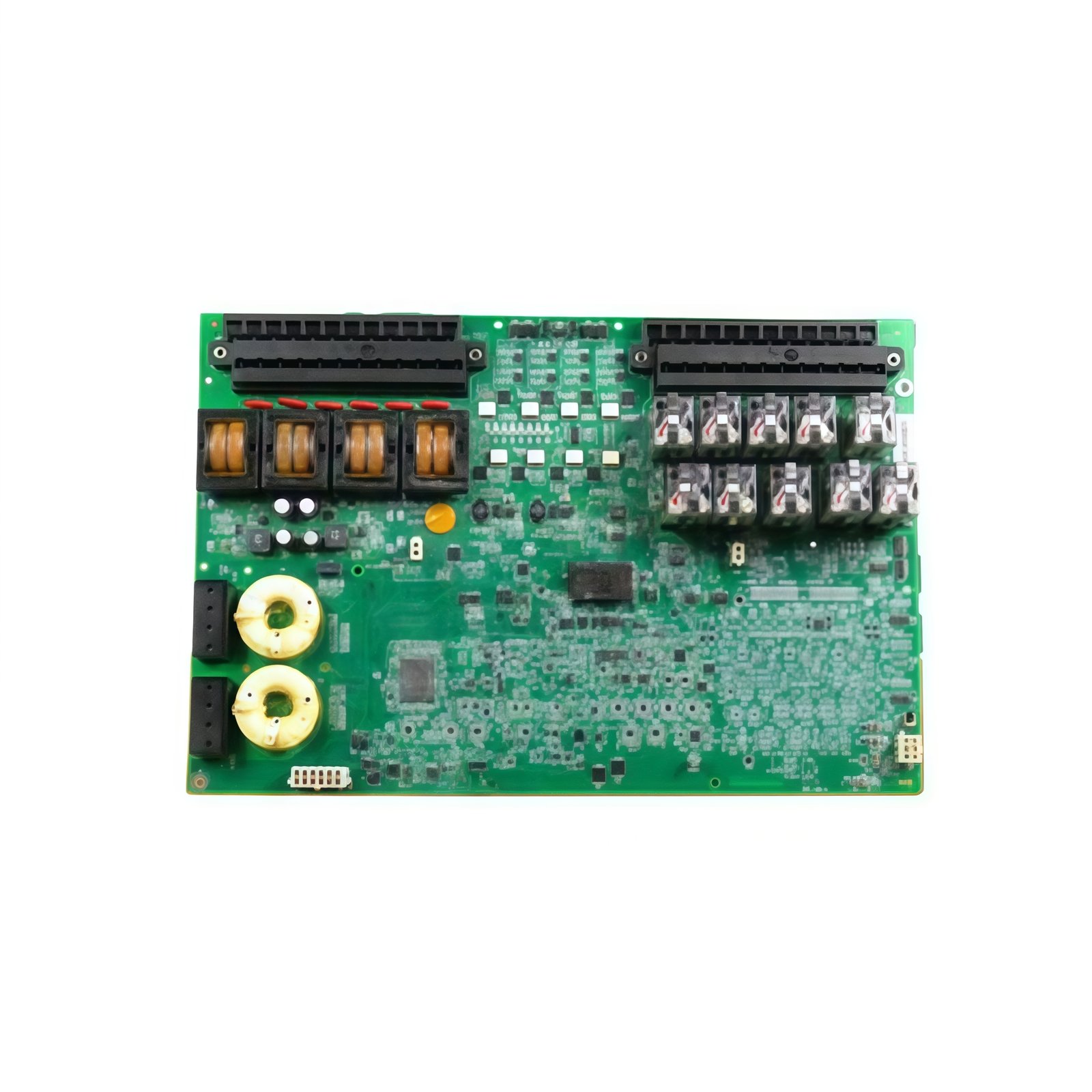
This GE IS200ESYSH2A IS200ESYSH2AAA High Speed Serial Board provides high-speed serial communication for Mark VI control systems. The board manages data exchange between the main controller and external devices. You will find this component in many GE turbine control applications worldwide. The IS200ESYSH2AAA variant includes the standard factory configuration without conformal coating.
Technical Specifications
| Parameter | Specification |
|---|---|
| Full Model | GE IS200ESYSH2A IS200ESYSH2AAA High Speed Serial Board |
| Category | High Speed Serial Board |
| Serial Ports | 4 Independent RS-232/RS-485 Ports |
| Maximum Baud Rate | 115.2 kbps (RS-232), 1 Mbps (RS-485) |
| Protocol Support | Modbus RTU, DNP 3.0, User-Defined |
| FIFO Buffer | 64 Bytes per Port |
| Isolation | 2500 V RMS (Port to Logic) |
| Dimensions (H x W) | 230 mm x 160 mm |
| Weight | Approximately 0.72 kg |
| Connectors | 4 x DB9, 1 x 50-Pin Header |
| Component Count | 156 Discrete Components |
| Energy Storage | 4 x 10 µF Decoupling Capacitors |
Serial Communication and Data Handling Features
The GE IS200ESYSH2A IS200ESYSH2AAA High Speed Serial Board supports multiple protocols on each port independently. Each channel includes a large FIFO buffer to prevent data overruns. The board handles CRC generation and checking without CPU intervention. Furthermore, it provides hardware flow control for RS-232 connections. Consequently, your system communicates reliably with PLCs, HMIs, and remote I/O devices.
Installation and Connection Steps
Mount this GE IS200ESYSH2A IS200ESYSH2AAA High Speed Serial Board in any Mark VI rack slot. First, connect serial cables to the four DB9 ports securely. After that, set the port configuration using the onboard DIP switches. Then, attach the 50-pin header to the VME backplane adapter. Finally, verify each port’s activity LEDs flash during data transmission.
Energy Discharge and Safety Notice
This GE IS200ESYSH2A IS200ESYSH2AAA High Speed Serial Board stores minimal energy in its capacitors. However, you must wait 30 seconds after power removal before handling. The four decoupling capacitors discharge through internal resistors. Never connect or disconnect serial cables while the board remains powered.
Status Indication and Diagnostics
Four green LEDs indicate valid power and initialization for each port. Four yellow LEDs flash during active data transmission on each channel. A red LED illuminates when any port detects a parity or framing error. These indicators help technicians troubleshoot communication issues without protocol analyzers.
Details
| Weight | 0.1 kg |
|---|---|
| Dimensions | 25 × 108 × 127 mm |
Reviews
There are no reviews yet.