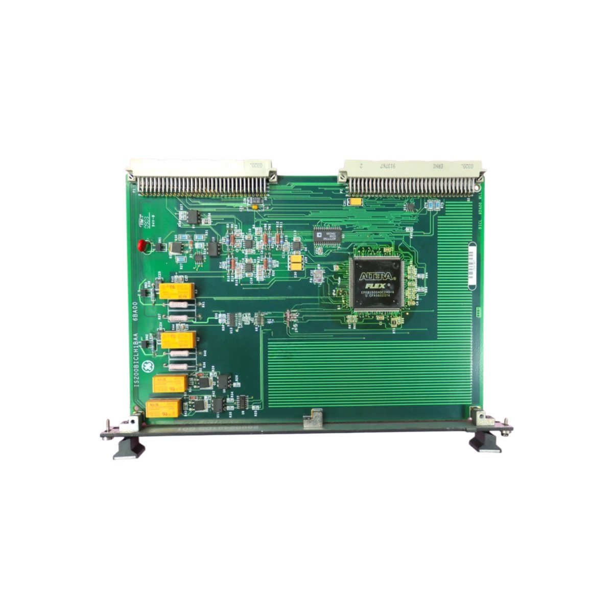
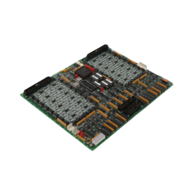
This GE IS200ESBPG1A IS200ESBPG1ABA Simplex Backup Circuit Board provides redundant protection for critical turbine control signals. The board monitors primary system health and switches to backup when necessary. You will find this component in many GE Mark VI control systems. The IS200ESBPG1ABA variant includes the standard factory configuration without conformal coating.
Technical Specifications
| Parameter | Specification |
|---|---|
| Full Model | GE IS200ESBPG1A IS200ESBPG1ABA Simplex Backup Circuit Board |
| Category | Simplex Backup Circuit Board |
| Monitoring Channels | 8 Critical Signal Inputs |
| Backup Switching Time | Less than 5 milliseconds |
| Output Relay | 2 Form C Relays (10A, 250V AC) |
| Watchdog Timer | Programmable from 10 ms to 10 seconds |
| Isolation | 2500 V RMS between Circuits |
| Dimensions (H x W) | 200 mm x 140 mm |
| Weight | Approximately 0.85 kg |
| Connectors | 2 x 20-Pin Headers, 1 x Terminal Block |
| Component Count | 168 Discrete Components |
| Energy Storage | 4 x 100 µF Hold-Up Capacitors |
Redundancy and Protection Features
The GE IS200ESBPG1A IS200ESBPG1ABA Simplex Backup Circuit Board monitors primary controller health continuously. A programmable watchdog timer detects when the primary system stops responding. The board then switches control outputs to the backup system automatically. Furthermore, it includes manual override switches for maintenance testing. Consequently, your turbine continues operating safely even if the primary controller fails.
Installation and Connection Steps
Mount this GE IS200ESBPG1A IS200ESBPG1ABA Simplex Backup Circuit Board in any Mark VI rack slot. First, connect primary and backup system signals to the terminal block. After that, wire the output relays to the critical control circuits. Then, set the watchdog timeout using the onboard DIP switches. Finally, test the automatic switchover by removing power from the primary controller.
Energy Discharge and Safety Notice
This GE IS200ESBPG1A IS200ESBPG1ABA Simplex Backup Circuit Board stores minimal energy in its capacitors. However, you must wait 30 seconds after power removal before handling. The four hold-up capacitors discharge through internal resistors. Never test the backup switchover while the turbine is running.
Status Indication and Diagnostics
A green LED indicates the primary system is healthy and active. A yellow LED illuminates when the backup system has control authority. A red LED flashes during the watchdog timeout warning period. Two additional LEDs show the state of each output relay clearly.
Details
| Weight | 0.1 kg |
|---|---|
| Dimensions | 25 × 108 × 127 mm |
Reviews
There are no reviews yet.