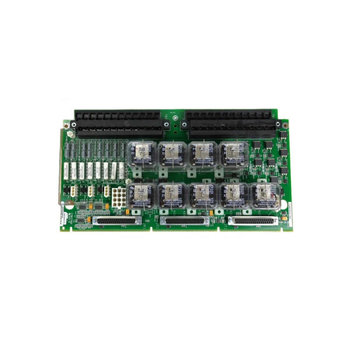
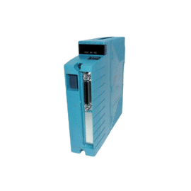
The GE IS200EPBPG1A IS200EPBPG1ACD distributes power and signals within the EX2100 exciter rack. This backplane board connects multiple exciter modules to common power buses. Therefore, it eliminates point-to-point wiring between individual exciter cards.
Product Overview
We designed this backplane board as the central backbone for exciter systems. Its heavy copper traces carry high currents to all connected modules. Moreover, this unit includes integrated fuses for each power distribution path.
Technical Specifications
| Parameter | Specification |
|---|---|
| Dimensions | 43.2 cm (length) x 33.0 cm (width) |
| Weight | 1.45 kg (approximately 3.20 lb) |
| Interface Type | 14 card edge connectors plus 2 power input terminals |
| Component Count | 98 components including fuses and terminal blocks |
| Energy Storage | No energy storage components on this board |
| Card Slots | 14 slots for exciter control and power modules |
| Power Bus Rating | 250A continuous at 600V DC |
| Signal Bus | 64 parallel lines with 2 oz copper traces |
| Fuse Protection | Individual 15A fast-blow fuses per power rail |
| Operating Temperature | -20°C to +70°C ambient |
| Board Material | FR-4 with high TG rating for thermal stability |
| Connector Type | 96-pin DIN 41612 for each slot |
Backplane Architecture
The GE IS200EPBPG1A IS200EPBPG1ACD uses separate plane layers for power and signals. Its heavy copper planes minimize voltage drop across the board length. Additionally, the board implements a star ground configuration for noise reduction. You get clean power delivery to all modules without ground loop issues.
Energy Storage Note
This backplane contains no capacitors or other energy storage components. All bulk energy storage resides on individual exciter modules instead. Therefore, you can handle this board without any discharge delay. However, always verify that external power sources are disconnected before touching the board.
Power Distribution
The board accepts DC power through two heavy-duty terminal blocks. Positive bus connects to all even-numbered slot pins simultaneously. Negative bus connects to all odd-numbered slot pins in parallel. Each power rail includes a 15A fuse located near the input terminals. A blown fuse indicates a fault in a specific exciter module.
Installation Steps
Mount this backplane inside the exciter cabinet using eight M6 screws. Ensure the board sits perfectly flat against the mounting studs. Then install all exciter modules into their designated slots. Tighten each module’s retaining screws to 0.8 Nm torque. Finally, connect the external DC power cables to the input terminals.
Signal Routing
The backplane carries 64 parallel signal lines between all slots. These signals include gate firing commands and status feedback. Board-to-board communication uses differential pairs for noise immunity. A dedicated slot 0 position holds the exciter system controller. All other slots communicate directly with the controller through the backplane.
Slot Assignment
Slot 0 accepts the main exciter control board exclusively. The GE IS200EPBPG1A IS200EPBPG1ACD has silkscreened labels for each slot.
Maintenance Guidelines
Inspect all fuses annually using a continuity tester. Replace any blown fuse with the exact 15A fast-blow type. Check the edge connectors for signs of arcing or discoloration. Clean any dirty contacts with isopropyl alcohol and a soft brush. Replace the entire backplane if you see cracked traces or burnt areas.
Application Scope
This backplane works in EX2100 and EX2100e excitation systems. Many synchronous generators use the GE IS200EPBPG1A IS200EPBPG1ACD for field control. Its robust design handles the high currents of large generator excitation.
Details
| Weight | 0.1 kg |
|---|---|
| Dimensions | 25 × 108 × 127 mm |
Reviews
There are no reviews yet.