The GE IS200EHPAG1D IS200EHPAG1DCB Pulse Amplifier Board amplifies low-energy pulses from the controller. This board drives gate signals for high-power SCRs and thyristors. You will find it in exciter firing circuits for generator field control. It converts TTL-level pulses into high-current gate drives.
Core Technical Specifications
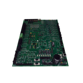
The GE IS200EHPAG1D IS200EHPAG1DCB Pulse Amplifier Board measures 31.5 cm in width and 23.0 cm in height. Its board thickness equals 2.5 cm including component height. The total assembly weighs approximately 0.82 kilograms. Twelve independent pulse amplifier channels occupy the board’s surface. Each channel accepts a 5 VDC TTL input pulse.
| Parameter | Specification |
|---|---|
| Amplifier Channels | 12 Independent Channels |
| Input Signal | 5 VDC TTL (Positive Edge Triggered) |
| Output Voltage | 24 VDC or 30 VDC (Field Selectable) |
| Output Current | 1.5 A Peak per Channel |
| Pulse Width Range | 10 µs to 200 µs (Programmable) |
| Dimensions (W x H x D) | 31.5 cm x 23.0 cm x 2.5 cm |
| Weight | 0.82 kg (approx) |
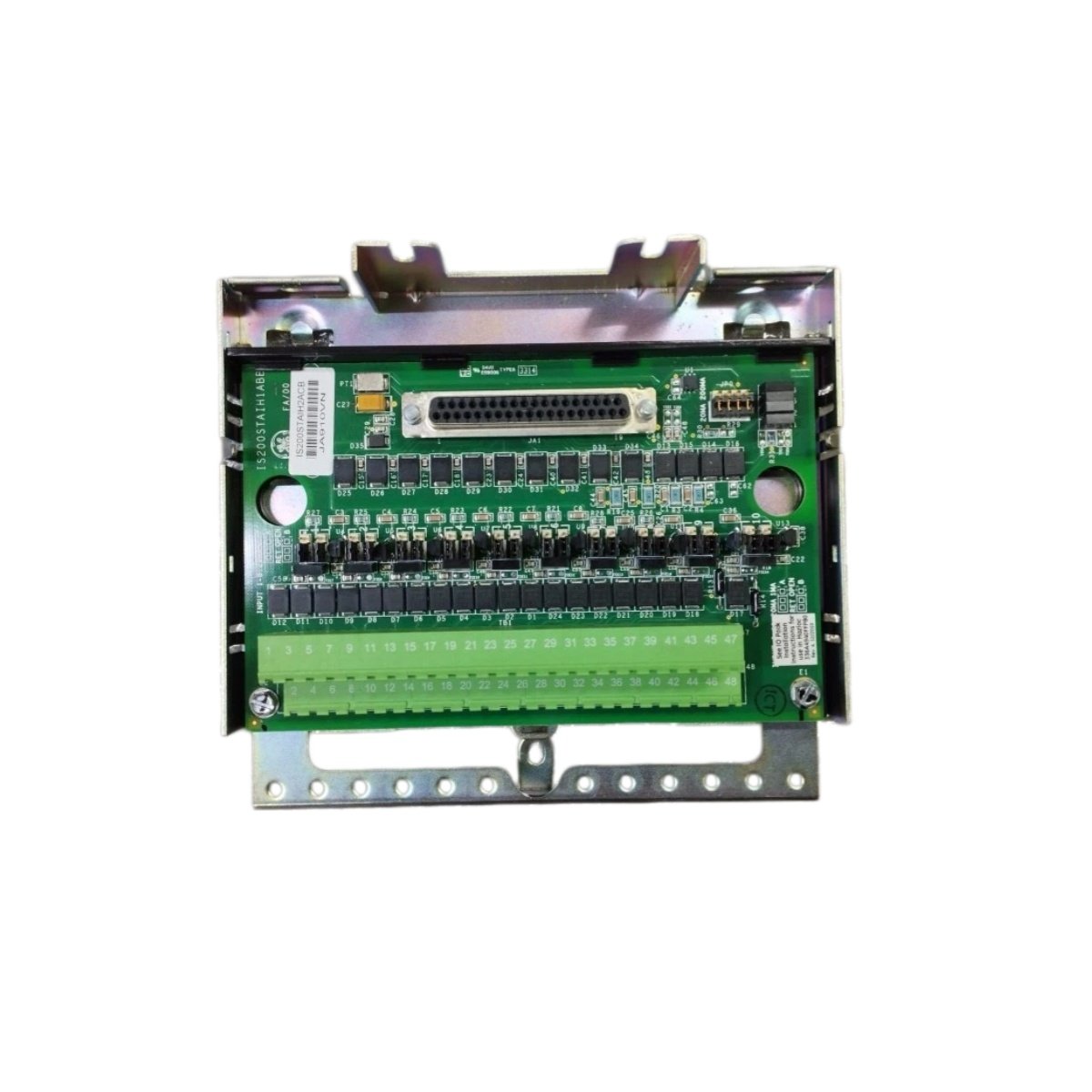
Connectors and Status Monitoring
The GE IS200EHPAG1D IS200EHPAG1DCB Pulse Amplifier Board uses one 50-pin header connector for input signals. This connector receives all twelve TTL pulses from the main controller. Two 9-pin D-sub connectors provide output wiring to SCR gate terminals. Twelve yellow LEDs flash for each active output pulse. A green LED confirms 24 VDC logic power presence. Moreover, a red LED indicates a short circuit on any output channel.
Energy Storage and Isolation Features
This pulse amplifier board contains small ceramic capacitors only for noise filtering. Therefore, it stores negligible energy after power removal. Each channel includes a pulse transformer for complete galvanic isolation. This transformer separates the logic ground from the floating gate drive. Furthermore, the GE IS200EHPAG1D IS200EHPAG1DCB Pulse Amplifier Board integrates gate clamping diodes on every output. These diodes protect the SCR gates from overvoltage spikes. You can select output voltage via a jumper block on the board. Set the jumper to 24 VDC for standard SCRs. Set it to 30 VDC for high-sensitivity thyristors. Do not exceed 1.5 A peak current per channel. Maintain proper creepage distance between high-voltage traces.
Details
| Weight | 0.1 kg |
|---|---|
| Dimensions | 25 × 108 × 127 mm |
Reviews
There are no reviews yet.