
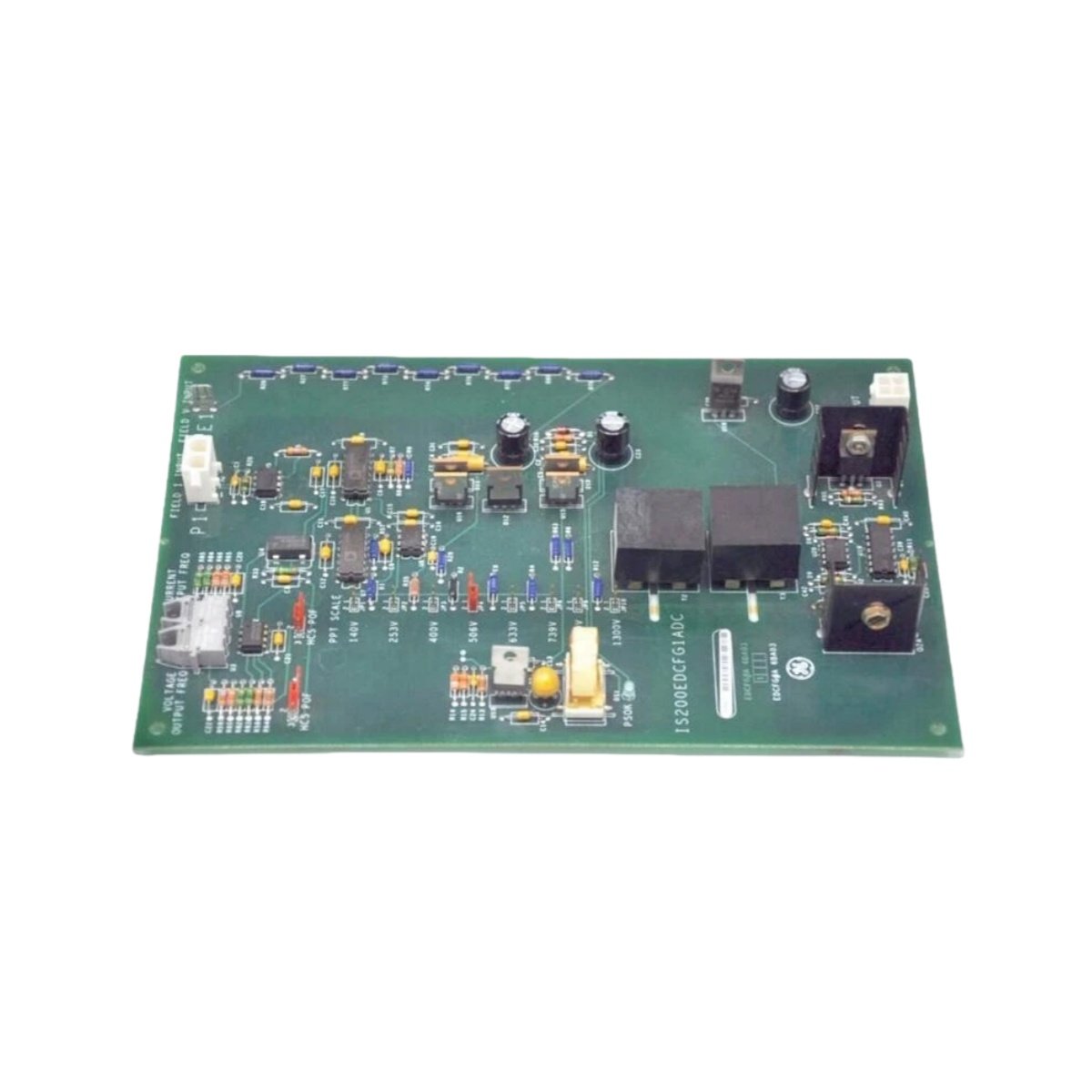
Board Function and System Integration
This DC feedback I/O terminal board interfaces between the excitation system and the main controller. It provides termination points for DC voltage and current feedback signals from power equipment. The board supports up to 16 analog input channels for monitoring various parameters. It also includes dedicated terminals for shield connections to reduce electrical noise. Consequently, this board plays a vital role in generator excitation control systems.
Technical Specifications
| Parameter | Specification |
|---|---|
| Brand | GE |
| Model Number | IS200EDCFG1A |
| Analog Input Channels | 16 differential inputs |
| Input Signal Types | 0–10 VDC, 4–20 mA |
| Input Impedance (Voltage) | >10 MΩ |
| Input Impedance (Current) | 250 Ω |
| Resolution | 12 bits |
| Accuracy | ±0.1% of full scale |
| Operating Temperature | –30°C to +65°C |
| Storage Temperature | –40°C to +85°C |
| Humidity | 10% to 90% non-condensing |
| Dimensions (H x W x D) | 150 mm x 100 mm x 25 mm |
| Weight | 0.30 kg |
| Termination Type | Screw-clamp terminals |
| Wire Gauge | 16–22 AWG |
| Connector Type | 50-pin ribbon cable to processor |
| Isolation | 1500 VAC (channel-to-backplane) |
| Status Indicators | Power and channel health LEDs |
| Mounting | Panel mount with screws |
| Vibration Tolerance | 1.0 G (10–55 Hz) |
Signal Processing and Feedback Monitoring
The IS200EDCFG1A captures DC feedback signals from exciter field windings and power converters. It conditions these signals for accurate interpretation by the control processor. Each channel includes a precision voltage divider or shunt resistor for scaling. The board provides low-pass filtering to eliminate high-frequency switching noise. This ensures stable and accurate feedback for closed-loop control.
Termination Design and Wiring Interface
Screw-clamp terminals accept solid or stranded wires from 16 to 22 AWG. Each channel provides two termination points for signal positive and negative leads. The board includes a dedicated shield terminal bar for cable drain connections. Numbered terminal blocks simplify identification during installation and maintenance. This organized layout reduces wiring errors and speeds up commissioning.
System Integration with Excitation Control
This terminal board connects to the main excitation controller via a 50-pin ribbon cable. The cable transmits all 16 feedback signals simultaneously to the processor. The board uses a standard pinout compatible with GE excitation systems. Proper cable orientation ensures correct signal routing to the processor. This integration enables precise voltage and current regulation in generator systems.
Power Requirements and Energy Characteristics
The board derives its power from the system backplane through the ribbon cable. It draws 150 mA from the 5 VDC supply during normal operation. Internal capacitors provide noise filtering for stable signal acquisition. The board dissipates approximately 3.0 W of heat under full load. This low power consumption reduces thermal stress on components.
Installation and Mounting Procedure
Mount the board securely to the cabinet panel using the four corner screws. Ensure proper alignment before tightening the mounting hardware. Connect the ribbon cable to the processor module after board installation. Route field wiring through cable entry points before termination. Tighten each terminal screw to 0.4–0.5 Nm torque for reliable connections.
Environmental Performance and Durability
This board operates reliably from –30°C to +65°C ambient temperatures. It withstands humidity levels between 10% and 90% without condensation. The PCB includes conformal coating for protection against contaminants. This rugged construction suits power plant and heavy industrial environments. Ensure adequate clearance around the board for ventilation.
Maintenance and Troubleshooting Tips
Inspect terminal connections periodically for tightness and oxidation. Clean the board gently using compressed air to remove dust accumulation. Check the ribbon cable for damage or loose connections. Replace the board if feedback signals show erratic behavior. Document all maintenance activities for regulatory compliance purposes.
Details
| Weight | 0.3 kg |
|---|---|
| Dimensions | 150 × 100 × 25 mm |
Reviews
There are no reviews yet.