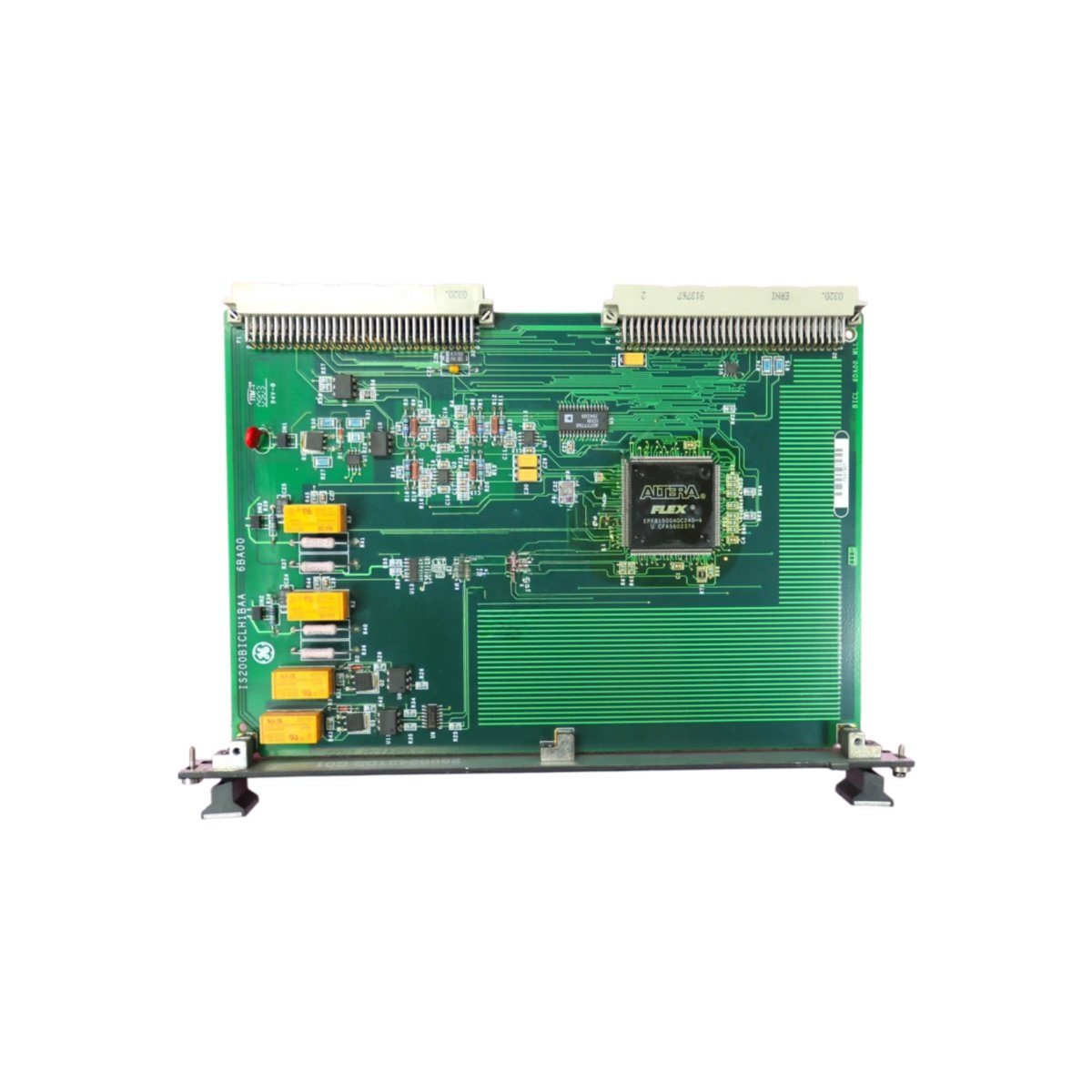
The GE IS200ECTBG2A IS200ECTBG2ADE exciter contact terminal board connects field contactors to Mark VI systems. This board provides a secure interface between exciter contact devices and control modules. You will find this terminal board in GE Mark VI exciter control cabinets. Its rugged design ensures reliable operation for contactor control circuits.
Contact Termination Architecture
This exciter terminal board provides forty screw terminal connections for contact wiring. Consequently, you can connect multiple contactors and auxiliary switches without additional hardware. The GE IS200ECTBG2A IS200ECTBG2ADE includes built-in surge suppression on each channel. Moreover, clearly marked terminals simplify wiring and troubleshooting. You can terminate wires quickly using standard slotted screwdrivers.
Technical Specifications
| Parameter | Value |
|---|---|
| Terminal Count | 40 (screw clamp type) |
| Wire Gauge Range | 22 AWG to 14 AWG (0.34 to 2.0 mm²) |
| Voltage Rating | 250V AC / 150V DC maximum |
| Current Rating | 3A per terminal continuous |
| Surge Protection | MOV, 275V AC clamp, 1500W peak |
| Contact Material | Brass with nickel plating |
| Torque Specification | 0.5 Nm (4.4 lb-in) |
| Dimensions | 280mm x 170mm x 30mm |
| Weight | 0.68 kg (1.50 lbs) |
| PCB Layers | 4 |
| Onboard Components | 40 terminals, 40 MOVs, 2 jumpers, 1 ground bar |
| Connector Count | 2 (ribbon cable to I/O, ground stud) |
| Status Indicators | None (passive termination) |
| Energy Storage | None (passive board) |
| Isolation Voltage | 1500V (terminal to backplane) |
| Response Time | <5 ns (surge clamping) |
| Operating Temperature | -20°C to +60°C |
| Storage Temperature | -40°C to +85°C |
Surge Protection and Contact Wiring
The unit includes metal-oxide varistors across each terminal channel. Therefore, it clamps voltage spikes from contactor coil switching. This board replaces the IS200ECTBG2ADE version without any wiring changes. Simply remove the old board and install this one. GE designed this terminal board for single-slot installation. Hence, it fits directly into existing Mark VI rack positions.
Four PCB layers separate field wiring traces from backplane signals. Two connectors handle all signal and ground connections. The GE IS200ECTBG2A IS200ECTBG2ADE includes a dedicated ground bar for surge current return. Accordingly, it safely diverts transient energy away from sensitive circuits. This feature protects exciter controls from contactor switching surges.
Installation and Wiring Guide
You can terminate both stranded and solid copper wires securely. The screw clamps accept wires without special ferrules or lugs. The GE IS200ECTBG2A IS200ECTBG2ADE works with all GE Mark VI exciter I/O modules. Always strip 6-8 mm of insulation before inserting wires. Proper torque on terminal screws prevents loose connections over time.
Each MOV provides bi-directional surge protection for AC and DC circuits. The board includes two configuration jumpers for signal type selection. The GE IS200ECTBG2A IS200ECTBG2ADE simplifies contactor wiring for exciter systems. Installation requires only a flathead screwdriver for terminal connections. This board operates reliably in non-condensing environments with adequate clearance.
Details
| Weight | 0.1 kg |
|---|---|
| Dimensions | 25 × 108 × 127 mm |
Reviews
There are no reviews yet.