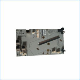
The GE IS200ECTBG1A IS200ECTBG1ADE Exciter Board manages contactor control for generator excitation circuits. This board interfaces between the Mark VI controller and high-power contactors. You will find it operating field flashing and de-excitation contactors. It plays a vital role in generator start-up and shutdown sequences.
Core Technical Specifications
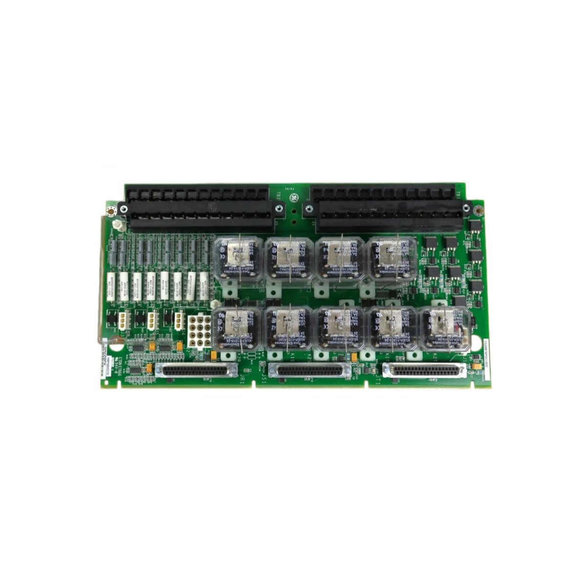
The GE IS200ECTBG1A IS200ECTBG1ADE Exciter Board measures 33.0 cm in width and 24.0 cm in height. Its board depth equals 2.8 cm including component clearance. The total assembly weighs approximately 1.8 kilograms. Twelve independent contactor driver channels populate the board. Each channel controls one external contactor via a solid-state relay.
| Parameter | Specification |
|---|---|
| Driver Channels | 12 Independent Contactor Drivers |
| Control Voltage | 120 VAC ±10%, 50/60 Hz |
| Output Type | Solid-State Relay (Zero-Crossing) |
| Maximum Load Current | 2 A per Channel (Continuous) |
| Input Logic | 24 VDC from Backplane |
| Dimensions (W x H x D) | 33.0 cm x 24.0 cm x 2.8 cm |
| Weight | 1.8 kg (approx) |
Connectors and Diagnostic Indicators
The GE IS200ECTBG1A IS200ECTBG1ADE Exciter Board uses two 64-pin DIN connectors for backplane communication. These connectors receive all 12 driver commands from the main processor. One 25-pin D-sub connector handles field wiring to external contactors. Twelve green LEDs illuminate for each active driver channel. A red LED indicates a blown fuse or overcurrent condition. Additionally, a yellow LED confirms 120 VAC supply presence.
Energy Storage and Protection Features
This exciter board contains small filter capacitors only on the 120 VAC input line. Consequently, it stores minimal residual energy after power disconnection. Each driver channel includes an internal snubber circuit for inductive load protection. This snubber reduces contact arcing during contactor de-energization. Moreover, the GE IS200ECTBG1A IS200ECTBG1ADE Exciter Board integrates individual fuse protection for each output. A blown fuse disables only that specific channel. You can replace fuses with the board mounted in the cabinet. Do not exceed 2 A continuously on any output channel. Maintain proper clearance around the board for heat dissipation.
Details
| Weight | 0.1 kg |
|---|---|
| Dimensions | 25 × 108 × 127 mm |
Reviews
There are no reviews yet.