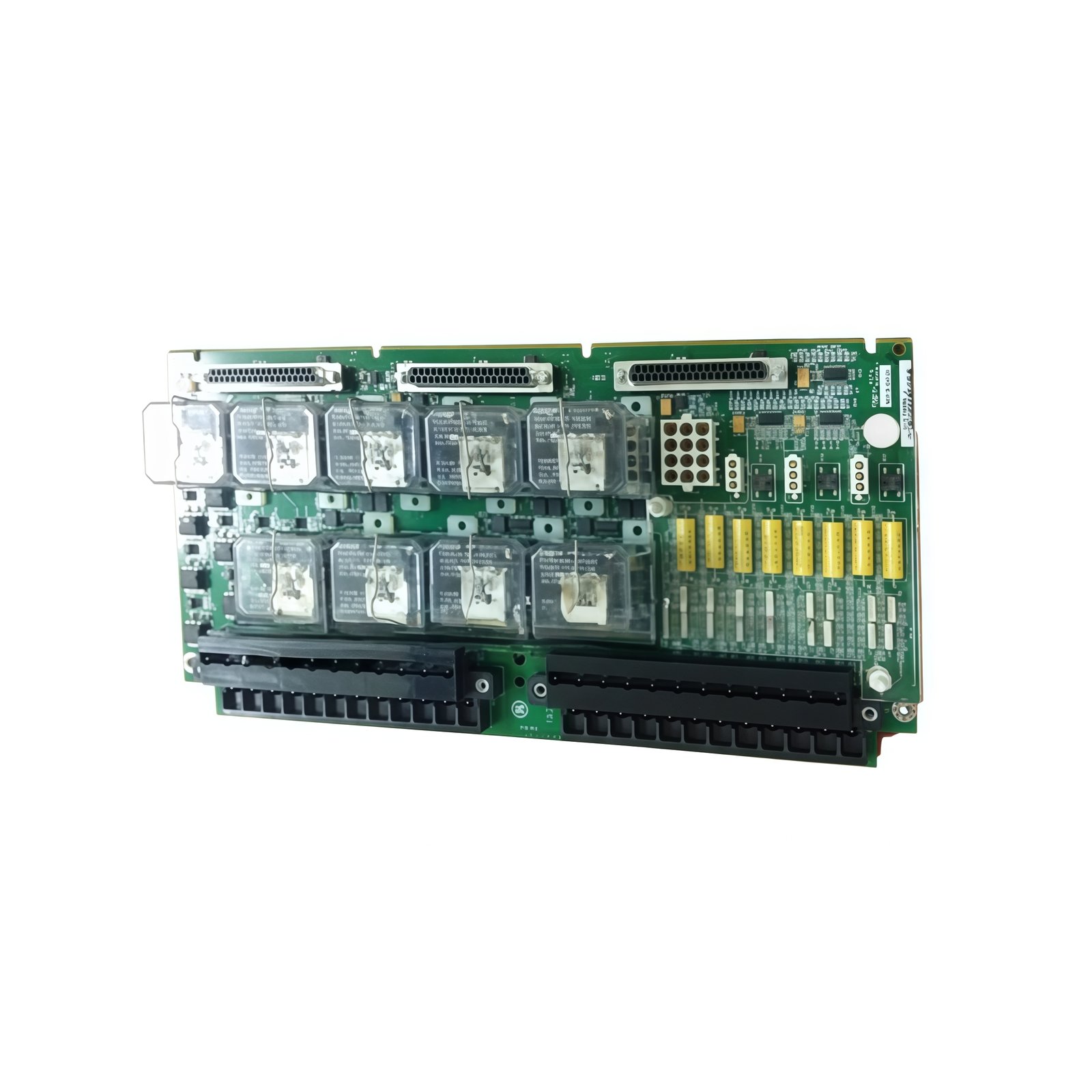
The GE IS200EBRGH2A exciter bridge interface board connects the controller to thyristor bridges. This board translates low-voltage gate signals into high-energy pulses for power semiconductors. You will find this interface board in GE Mark VI excitation systems. Its robust design withstands extreme electrical stress in exciter applications.
Bridge Interface Architecture
This interface board provides six gate drive channels for three-phase bridges. Consequently, it fires all thyristors in a full-bridge rectifier. The GE IS200EBRGH2A amplifies low-level control signals to high-current gate pulses. Moreover, each channel includes individual fault detection circuits. You can monitor gate status through the backplane interface.
Technical Specifications
| Parameter | Value |
|---|---|
| Gate Pulse Output | 6 channels, 24V/2A peak per channel |
| Pulse Width | 50-200 µS (software configurable) |
| Input Logic Level | 5V DC (from controller) |
| Output Voltage | 24V DC nominal for gate drive |
| Isolation Voltage | 2500V RMS (logic to gate side) |
| Dimensions | 240mm x 180mm x 35mm |
| Weight | 0.75 kg (1.65 lbs) |
| PCB Layers | 8 |
| Onboard Components | 6 pulse transformers, 12 diodes, 18 capacitors |
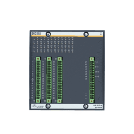
| Connector Count | 4 (logic input, gate output, fault feedback, power) |
| Status Indicators | 6 LEDs (one per channel, gate active) |
| Energy Storage | 4700 µF (gate drive power supply) |
| Maximum Switching Frequency | 5 kHz |
| Operating Temperature | -10°C to +55°C |
| Storage Temperature | -25°C to +70°C |
High Voltage Isolation and Gate Drive
The unit includes six pulse transformers for channel isolation. Therefore, each gate drive floats independently without ground loops. This board replaces the IS200EBRGH2A version without any logic changes. Simply remove the old board and install this one. GE designed this interface board for high-reliability applications. Hence, it meets stringent exciter system requirements.
Eight PCB layers separate low-voltage logic from high-voltage gate traces. Four connectors handle all input, output, and feedback signals. The GE IS200EBRGH2A holds 4700 µF of energy storage capacitance. Accordingly, it delivers consistent gate pulses during line voltage sags. Six LEDs indicate active gate pulses for every channel.
Fault Monitoring and Installation Guide
Each channel includes a fault detection circuit for shorted gates. The board reports open or shorted conditions to the main controller. The GE IS200EBRGH2A requires a clean 24V DC power supply. Always use high-voltage rated cables for gate output connections. Keep gate leads shorter than 2 meters for reliable operation.
Proper heatsinking around the pulse transformers ensures long life. The board includes thermal protection that shuts down at 85°C. The GE IS200EBRGH2A works with all GE Mark VI excitation systems. Installation requires only a screwdriver for power and signal connections. This board operates in non-condensing environments with adequate airflow.
Details
| Weight | 0.1 kg |
|---|---|
| Dimensions | 25 × 108 × 127 mm |


Reviews
There are no reviews yet.