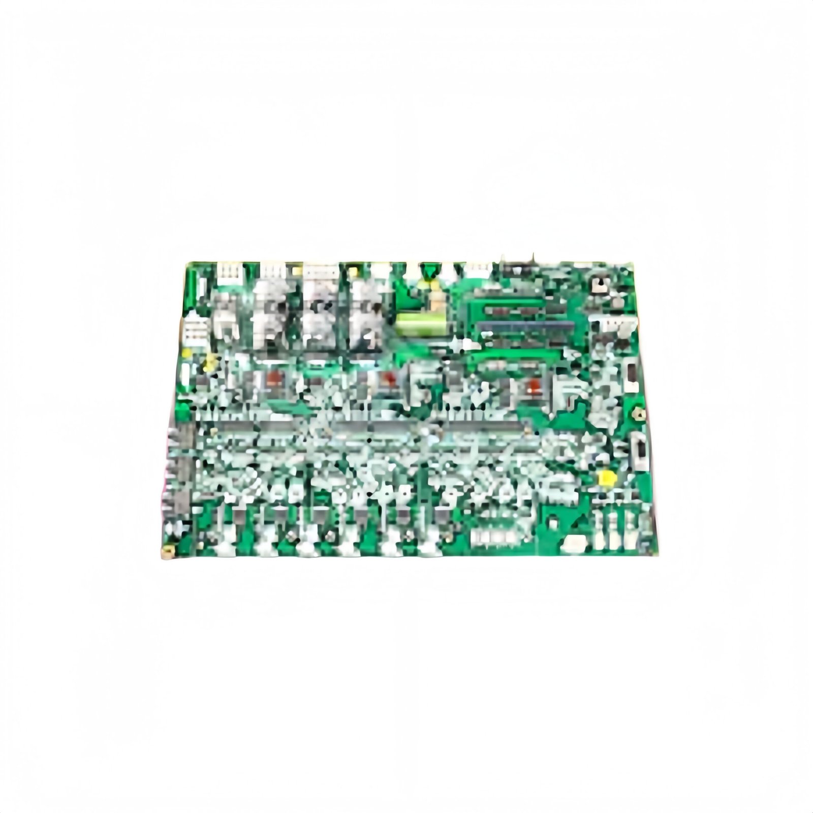
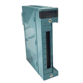
This GE IS200EAUXH1A IS200EAUXH1ABB Exciter Auxiliary I/O Interface Board manages auxiliary signals for generator excitation systems. The board interfaces between field devices and the main exciter controller. You will find this component in many GE Mark VI excitation applications. The IS200EAUXH1ABB variant includes a rugged conformal coating for harsh environments.
Technical Specifications
| Parameter | Specification |
|---|---|
| Full Model | GE IS200EAUXH1A IS200EAUXH1ABB Exciter Auxiliary I/O Interface Board |
| Category | Exciter Auxiliary I/O Interface Board |
| Analog Inputs | 8 Differential Channels (14-Bit, ±10V) |
| Analog Outputs | 4 Channels (12-Bit, 0-10V or 4-20mA) |
| Digital Inputs | 16 Opto-Isolated (24V DC) |
| Digital Outputs | 8 Relay Contacts (2A, 250V AC) |
| Update Rate | 500 Hz for All Channels |
| Dimensions (H x W) | 230 mm x 160 mm |
| Weight | Approximately 0.95 kg |
| Connectors | 2 x 50-Pin Ribbon Headers, 1 x Terminal Block |
| Component Count | 256 Discrete Components |
| Energy Storage | 8 x 10 µF Signal Capacitors |
Auxiliary I/O Processing Features
The GE IS200EAUXH1A IS200EAUXH1ABB Exciter Auxiliary I/O Interface Board handles diverse auxiliary field signals efficiently. A 14-bit ADC converts all analog inputs with 0.05% accuracy. The board provides loop power for 4-20mA two-wire transmitters directly. Furthermore, the relay outputs can switch AC or DC loads up to 2A. Consequently, this single board handles multiple auxiliary signal types for the exciter.
Installation and Connection Steps
Mount this GE IS200EAUXH1A IS200EAUXH1ABB Exciter Auxiliary I/O Interface Board in any Mark VI exciter cabinet slot. First, connect field wiring to the terminal block carefully. After that, attach the ribbon cables to the main exciter controller via the two headers. Then, set the channel configuration jumpers for your specific sensor types. Finally, verify each input and output using a known signal source.
Energy Discharge and Safety Notice
This GE IS200EAUXH1A IS200EAUXH1ABB Exciter Auxiliary I/O Interface Board stores minimal energy in its capacitors. However, you must wait 30 seconds after power removal before handling. The eight signal capacitors discharge through protection circuits during this time. Never apply voltages above the specified input range to any channel.
Status Indication and Diagnostics
A green LED indicates the board has power and communicates properly. A yellow LED flashes during active analog-to-digital conversion cycles. A red LED illuminates when any input exceeds the safe operating range. Eight individual LEDs show the status of each relay output clearly.
Details
| Weight | 0.1 kg |
|---|---|
| Dimensions | 25 × 108 × 127 mm |
Reviews
There are no reviews yet.