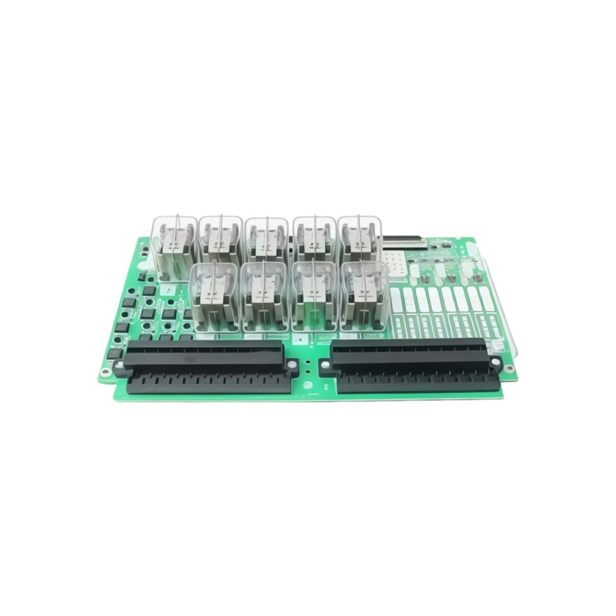
The GE IS200EACFG2B IS200EACFG2BAA Exciter Board provides closed-loop control for generator field excitation. This board manages SCR firing angles for precise voltage regulation. You will find it maintaining generator terminal voltage within ±0.5% of setpoint. It operates as a core component in GE Mark VI excitation systems.
Core Technical Specifications
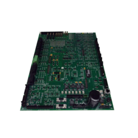
The GE IS200EACFG2B IS200EACFG2BAA Exciter Board measures 33.0 cm in width and 24.0 cm in height. Its board depth equals 2.8 cm including component clearance. The total assembly weighs approximately 0.9 kilograms. Six SCR gate drive channels occupy the board’s central area. Two fiber optic ports receive firing angle commands from the controller.
| Parameter | Specification |
|---|---|
| SCR Gate Channels | 6 Independent Channels (3-Phase Bridge) |
| Firing Angle Range | 0° to 180° (Software Controlled) |
| Input Control | 2 Fiber Optic Receivers (HFBR-2412) |
| AC Supply Voltage | 115 VAC ±10%, 50/60 Hz |
| DC Logic Supply | 24 VDC ±10%, 1.2 A Maximum |
| Isolation Voltage | 2500 Vrms (Gate to Logic) |
| Dimensions (W x H x D) | 33.0 cm x 24.0 cm x 2.8 cm |
| Weight | 0.9 kg (approx) |
Connectors and Monitoring Interfaces
The GE IS200EACFG2B IS200EACFG2BAA Exciter Board uses two 20-pin header connectors for internal signals. One 15-pin D-sub connector provides analog feedback monitoring outputs. Six green LEDs illuminate for each active gate pulse. A yellow LED confirms fiber optic link integrity. Moreover, a red LED signals a loss of synchronizing signal.
Feedback Inputs and Protection
This exciter board accepts three AC voltage feedback signals from the generator terminals. It also receives one DC current feedback from the field circuit. Each feedback input includes programmable scaling for different PT and CT ratios. The GE IS200EACFG2B IS200EACFG2BAA Exciter Board integrates overexcitation and underexcitation limiters. These limiters prevent generator damage during transient conditions.
Energy Storage and Thermal Management
This exciter board contains small filter capacitors only on power inputs. Therefore, it stores minimal residual energy after power disconnection. Each gate driver includes a pulse transformer for complete galvanic isolation. The board requires forced-air cooling for continuous operation at full load. You must mount this board vertically inside a Mark VI cabinet. Maintain 3 cm clearance around all heat-generating components. Do not disconnect fiber optic cables while power is active.
Details
| Weight | 0.1 kg |
|---|---|
| Dimensions | 25 × 108 × 127 mm |
Reviews
There are no reviews yet.