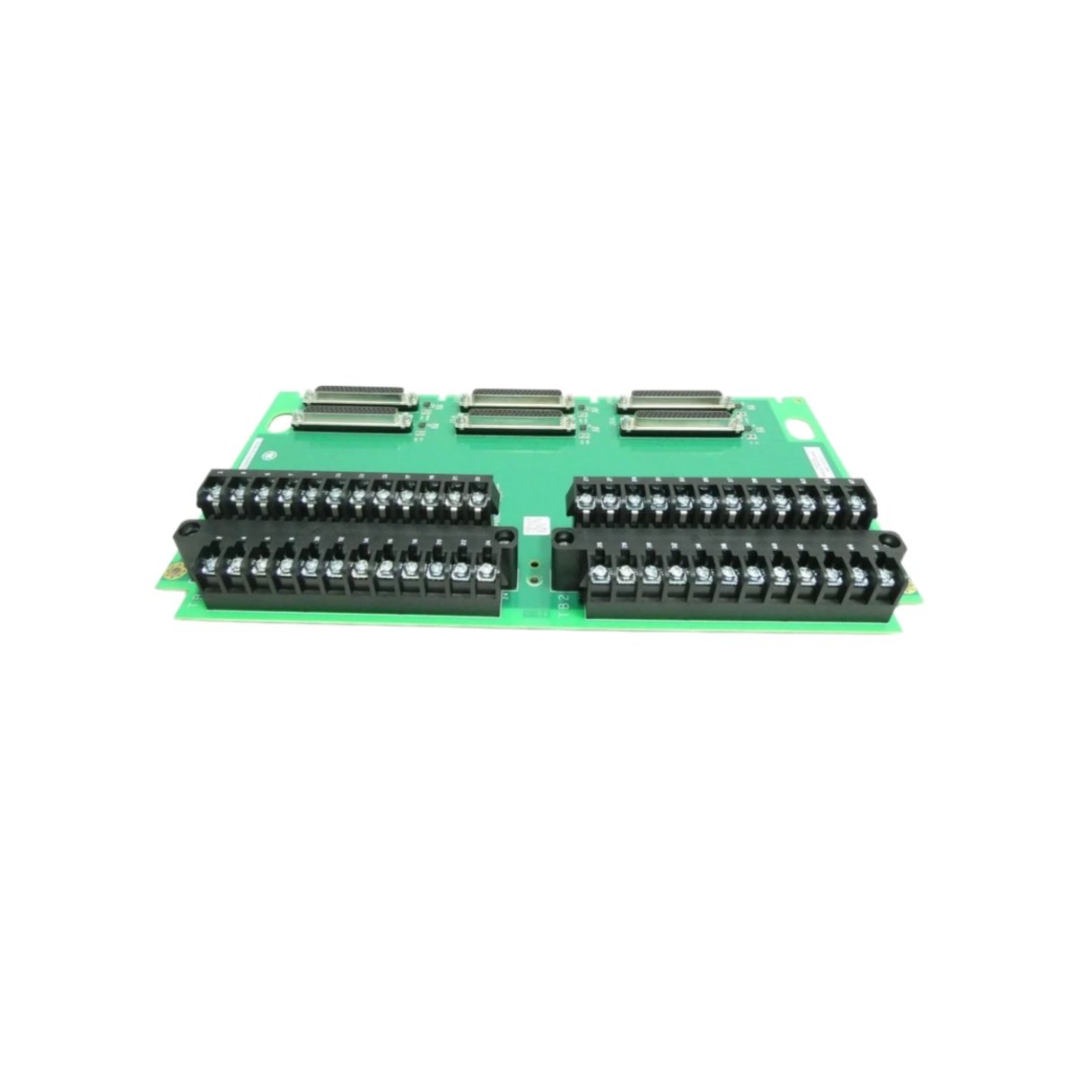
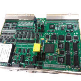
The GE IS200DSPXH1D IS200DSPXH1DBD processes digital signals for Mark VI turbine control systems. This board handles high-speed inputs from proximity probes and speed sensors. Therefore, it provides accurate timing measurements for turbine protection functions.
Product Overview
We designed this digital signal PCB for real-time processing of critical turbine parameters. Its dedicated DSP chip performs fast Fourier transforms for vibration analysis. Moreover, this unit includes onboard memory for buffering time-stamped data.
Technical Specifications
| Parameter | Specification |
|---|---|
| Dimensions | 27.9 cm (length) x 17.8 cm (width) |
| Weight | 0.48 kg (approximately 1.06 lb) |
| Interface Type | Dual 64-pin backplane connectors plus front I/O |
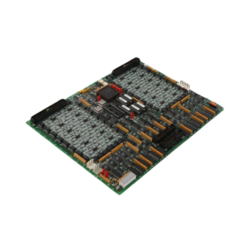
| Component Count | 236 components including DSP and programmable logic |
| Energy Storage | 8 aluminum capacitors (100 µF, 25V) plus 28 ceramic |
| Processor | 32-bit DSP at 150 MHz with hardware multiply-accumulate |
| Memory | 1 MB SRAM, 512 KB flash, 128 KB dual-port RAM |
| Input Channels | 16 high-speed digital inputs |
| Output Channels | 8 digital outputs for trip relays |
| Max Frequency | 100 kHz per input channel |
| Measurement Accuracy | ±0.01% for speed, ±1° for phase |
| Filtering | Programmable low-pass and notch filters |
DSP Architecture
The GE IS200DSPXH1D IS200DSPXH1DBD uses a dedicated digital signal processor chip. Its eight aluminum capacitors filter power for the DSP and memory circuits. Additionally, an onboard FPGA handles input debouncing and time-stamping. You get microsecond resolution for all turbine speed and phase measurements.
Energy Storage Components
Eight aluminum capacitors provide 15 ms of hold-up for the DSP during power dips. Twenty-eight ceramic capacitors decouple noise from every IC power pin. Each input channel includes a dedicated capacitor for debounce filtering. These capacitors eliminate false triggers from contact bounce or noise. Clean signals ensure accurate speed calculation for overspeed protection.
Input Signal Types
Channels 1 through 4 accept magnetic pickups for speed measurement.
Installation Steps
Insert this PCB into any Mark VI slot with dual backplane connectors. Align the GE IS200DSPXH1D IS200DSPXH1DBD with both card guide rails. Push the board evenly until both ejector levers lock into place. Then secure the board with its four corner mounting screws. Connect field wiring to the front 24-pin terminal block.
Speed Measurement Features
The board measures speed from magnetic pickup or proximity probe inputs. A dedicated hardware counter processes each input channel independently. The DSP calculates speed once per revolution for low-speed accuracy. Phase angle measurement compares input signals against a reference channel. For two-shaft turbines, you can measure differential speed between shafts.
Alarm and Trip Logic
Each input channel has two independently programmable setpoints. Setpoint 1 typically triggers an alarm at 105% of rated speed. Setpoint 2 triggers a turbine trip at 110% of rated speed. The onboard logic implements voting for redundant sensor configurations. Two-out-of-three voting prevents nuisance trips from a single sensor failure. All trip decisions occur within 10 ms of detecting an overspeed condition.
Application Notes
This digital signal PCB suits steam and gas turbine overspeed protection systems. Many power plants use the GE IS200DSPXH1D IS200DSPXH1DBD for critical safety functions. Its high accuracy meets API 670 standards for machinery protection.
Details
| Weight | 0.1 kg |
|---|---|
| Dimensions | 25 × 108 × 127 mm |
Reviews
There are no reviews yet.