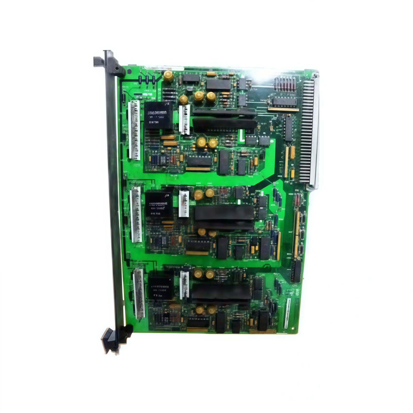
This printed circuit board provides digital output capability for GE Mark VIe turbine systems. It drives actuators, contactors, and indicator lamps directly from the controller. Therefore, it enables reliable discrete control for turbine sequencing and protection logic.
Physical and Output Specifications
The GE IS200DAMBG1A IS200DAMBG1ACB measures 26.0 cm in length and 18.5 cm in width. Moreover, its board weight equals approximately 0.56 kg for rack mounting. A single 64-pin male connector links this board to the VME backplane. Additionally, the board provides sixteen independent digital output channels.
| Parameter | Specification |
|---|---|
| Brand | General Electric (GE) |
| Full Model | IS200DAMBG1A IS200DAMBG1ACB |
| Category | Printed Circuit Board (Digital Output) |
| Dimensions (L x W) | 26.0 cm x 18.5 cm (10.24″ x 7.28″) |
| Board Weight | 0.56 kg (1.23 lbs) |
| Primary Interface | 1 x 64-pin Male Connector |
| Field Wiring Points | 20 Screw Terminal Blocks |
| Output Channels | 16 Independent Channels |
| Output Type | Transistor (NPN Sinking) |
| Output Voltage Range | 12 to 24 VDC |
| Output Current per Channel | 0.5 A (Continuous), 0.8 A (Peak) |
| Total Output Current | 6.0 A Maximum (All Channels Combined) |
| Output On-State Drop | < 1.2 VDC at 0.5 A |
| Output Off-State Leakage | < 0.1 mA at 24 VDC |
| Output Protection | Short Circuit + Overtemperature + Overcurrent |
| Output Response Time | 0.5 ms Maximum |
| Switching Frequency | 200 Hz Maximum (Resistive Load) |
| Common Configuration | 16 Outputs Share Two Commons (8 per Group) |
| On-Board Components | 16 Output Transistors + 16 Optocouplers + 16 Flyback Diodes + 2 Current Sense ICs + 8 Protection Diodes + 1 Voltage Regulator + 1 EMI Filter + 1 LED Driver IC + 1 Fuse |
| Energy Storage | 3 x 100 µF Electrolytic Capacitors (35V) + 3 x 10 µF Tantalum (25V) |
| Operating Voltage | +5 VDC and +24 VDC from Backplane |
| Isolation Rating | 1500 Vrms (Field to Backplane) |
| Operating Temperature | -20°C to +65°C (-4°F to +149°F) |
| Status Indicators | 16 Green LEDs (Output Status) + 1 Green LED (Power) + 1 Red LED (Fault) + 1 Green LED (24V OK) |
Digital Output Features and Protection Systems
The GE IS200DAMBG1A IS200DAMBG1ACB uses sixteen NPN sinking transistors for discrete output control. Specifically, each output delivers 0.5 amp continuously at 24 VDC. In addition, internal flyback diodes protect the transistors when driving inductive loads. Moreover, short circuit protection shuts down any faulty channel automatically. Furthermore, current sensing ICs monitor total load across each group of eight outputs. Thus, this board survives wiring mistakes without permanent damage.
High-Density Output Configuration
Sixteen output channels fit into a single Mark VIe rack slot with this board. For instance, you can control up to sixteen solenoid valves or indicator lamps with one module. In addition, the two common groups allow separate power supplies for different output banks. Moreover, the removable screw terminal blocks accept 18-22 AWG stranded or solid wires. Furthermore, each channel includes an independent green LED for visual status monitoring. Therefore, this board saves valuable rack space in large turbine control systems.
Energy Storage and Operational Stability
This printed circuit board stores energy using six onboard capacitors for power filtering. Specifically, three electrolytic capacitors smooth the 24 VDC supply for stable transistor operation. In addition, three tantalum capacitors provide high-frequency noise suppression for logic circuits. Furthermore, these capacitors maintain output status during brief power interruptions. Consequently, the GE IS200DAMBG1A IS200DAMBG1ACB continues operating through minor supply dips reliably.
Installation and Diagnostic Indicators
Nineteen LED indicators provide operational status at a glance on this board. First, a green Power LED lights when the 5 VDC backplane supply is present. Second, a green 24V OK LED indicates external load supply voltage is present. Third, sixteen green Output Status LEDs illuminate when each corresponding output channel turns on. Finally, a red Fault LED signals overtemperature or overcurrent conditions. Additionally, the board features six mounting holes for secure rack attachment. Thus, you can diagnose system status instantly without external tools.
Details
| Weight | 0.1 kg |
|---|---|
| Dimensions | 25 × 108 × 127 mm |

Reviews
There are no reviews yet.