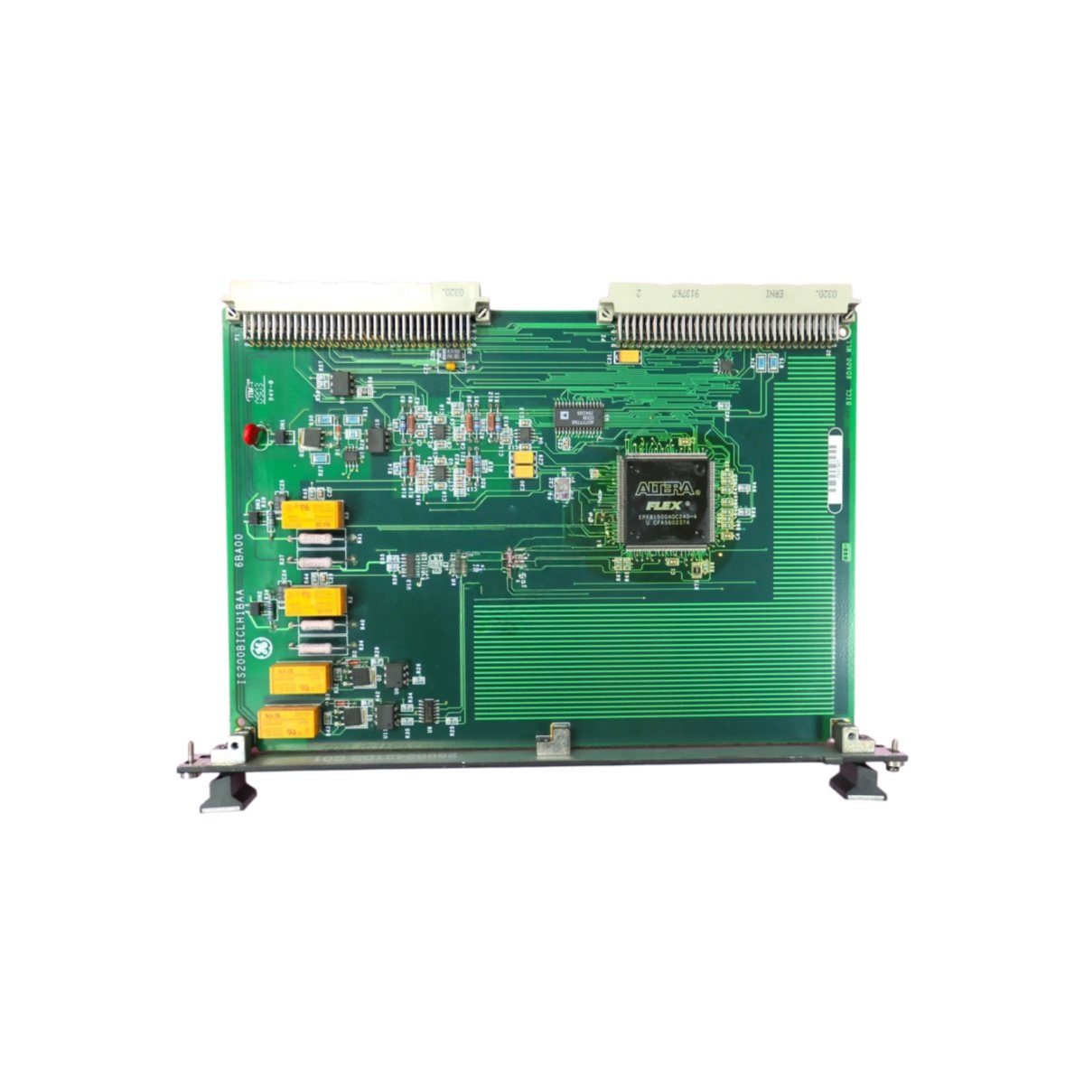
This Speedtronic turbine control board serves as the main processor for GE Mark VIe systems. It executes control algorithms for gas and steam turbine management. Therefore, it delivers reliable real-time control for power generation applications.
Physical and Processor Specifications
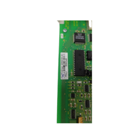
The GE IS200CPFXG1A IS200CPFXG1AAA measures 26.0 cm in length and 18.5 cm in width. Moreover, its board weight equals approximately 0.72 kg for rack mounting. A single 64-pin male connector links this board to the VME backplane. Additionally, the processor includes built-in communication ports and extensive memory.
| Parameter | Specification |
|---|---|
| Brand | General Electric (GE) |
| Full Model | IS200CPFXG1A IS200CPFXG1AAA |
| Category | Speedtronic Turbine Control Board |
| Dimensions (L x W) | 26.0 cm x 18.5 cm (10.24″ x 7.28″) |
| Board Weight | 0.72 kg (1.59 lbs) |
| Primary Interface | 1 x 64-pin Male Connector |
| Processor Type | 32-bit RISC (200 MHz) |
| Program Memory | 2 MB RAM (Battery Backed) |
| Data Memory | 1 MB RAM (Retentive with Battery) |
| Flash Memory | 4 MB (Firmware Storage) |
| Backup Battery | Internal Lithium (3V, 5 Year Life) |
| Execution Speed | 0.1 µs per Boolean Instruction |
| Built-In Communication Ports | 2 x RS-232 + 1 x RS-485 + 1 x Ethernet |
| Supported Protocols | Modbus RTU/TCP + GE Proprietary + OPC |
| Ethernet Baud Rate | 10/100 Mbps |
| Memory Expansion Slot | Yes (CompactFlash, Up to 1 GB) |
| Maximum Digital I/O | 4096 Points (with Expansions) |
| Maximum Analog I/O | 512 Channels (with Expansions) |
| Programming Languages | Ladder Diagram (LD) + Function Block (FBD) + C |
| Task Types | Cyclic + Periodic + Event + Interrupt |
| On-Board Components | 1 CPU IC + 6 Memory Chips + 3 UARTs + 1 Ethernet Controller + 1 RTC + 3 Line Drivers + 4 Optocouplers + 12 Protection Diodes + 1 Voltage Regulator |
| Energy Storage | 4 x 470 µF Electrolytic Capacitors (35V) + 4 x 10 µF Tantalum (25V) + 1 x CR2032 Backup Battery |
| Battery Backup Time | 5 Years (Typical for RAM and RTC Retention) |
| Scan Time | 0.5 ms per 1 kB of Ladder Logic |
| Operating Temperature | -20°C to +65°C (-4°F to +149°F) |
| Status Indicators | 1 Green LED (Power) + 1 Green LED (Run) + 1 Red LED (Fault) + 1 Yellow LED (Battery Low) + 3 Yellow LEDs (Port Activity) + 1 Green LED (Ethernet Link) + 1 Yellow LED (Ethernet Activity) |
Processing Performance and Memory Architecture
The GE IS200CPFXG1A IS200CPFXG1AAA features a 200 MHz 32-bit RISC processor for high-speed control. Specifically, the 2 MB program memory stores complex turbine control algorithms. In addition, the 1 MB data memory holds process variables and retentive values. Moreover, the execution speed of 0.1 µs per Boolean instruction ensures extremely fast response. Furthermore, a lithium battery retains RAM contents for up to five years. Consequently, this Speedtronic board delivers high-performance control for demanding turbine applications.
Communication Ports and Expansion Capabilities
You will find four communication ports on this turbine control board. For instance, two RS-232 ports support Modbus RTU for HMI and SCADA connectivity. In addition, one RS-485 port handles GE proprietary networks for legacy device communication. Moreover, the Ethernet port supports Modbus TCP and OPC for plant-wide integration. Furthermore, the CompactFlash slot accepts memory cards for program backup up to 1 GB. Thus, this processor integrates seamlessly into Mark VIe turbine control architectures.
Built-In Real-Time Clock and Task Management
This Speedtronic board includes a real-time clock for time-stamped events. Specifically, the clock retains date and time during power loss using battery backup. In addition, the CPU supports cyclic, periodic, event, and interrupt tasks flexibly. Moreover, a built-in watchdog timer monitors program execution for faults continuously. Furthermore, the processor can execute C language blocks for complex mathematical operations. Therefore, the GE IS200CPFXG1A IS200CPFXG1AAA meets demanding response time requirements for turbine control.
Installation and Diagnostic Indicators
Nine LED indicators provide operational status at a glance on this board. First, a green Power LED lights when the backplane supply voltages are present. Second, a green Run LED flashes during normal program execution. Third, a red Fault LED indicates hardware or software errors. Fourth, a yellow Battery Low LED warns when the backup battery needs replacement. Additionally, three yellow Port Activity LEDs illuminate during data transmission or reception on serial ports. Finally, a green Ethernet Link LED lights when the network cable is connected, and a yellow Ethernet Activity LED flashes during traffic. Furthermore, the board features six mounting holes for secure rack attachment. Thus, you can diagnose system health instantly without external tools.
Details
| Weight | 0.1 kg |
|---|---|
| Dimensions | 25 × 108 × 127 mm |
Reviews
There are no reviews yet.